
0
Owner's of the Panasonic Camcorder Memory Card Camera-Recorder gave it a score of 0 out of 5. Here's how the scores stacked up:

– 67 –
Chapter 4 Adjustments and Settings for Recording — Setting the time data
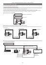
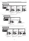
External lock operation procedure
To externally lock the time code, follow the steps below.
1
Set the <TCG> switch to <F-RUN>.
2
Set the <DISPLAY> switch to <TC>.
3
Set [GL IN] or [SDI IN] in the main menu → [I/F SETUP] → [GENLOCK] → [GENLOCK].
4
Input a reference time code and reference video signal that are in a phase relationship (that conforms to time code specifications)
to the <TC IN> and <GENLOCK IN> terminals or <SDI IN> terminal, respectively.
The built-in time code generator is locked to the reference time code. When approximately ten seconds has elapsed after locking, the external lock
status will be held even if the reference time code from the external device is disconnected.
fWhen the input reference signal of generator lock is disrupted, recording cannot be performed normally. [TEMPORARY PAUSE IRREGULAR SIG]
is displayed in the viewnder screen, and the clip is divided. The continuity of the time code is not guaranteed. Recording resumes when the signal
returns to normal. However, during loop recording, recording does not resume.
fWhen the time code is externally locked, the time code is instantaneously locked to the external time code, the same value as the value of the
external time code is output to the counter display area. Do not set to the recording mode for several seconds until the sync generator has
stabilized. Furthermore, lock the time code to the <TC IN> terminal signal. The time code of the HD SDI signal input from the <SDI IN> terminal is
not locked.
fWhen [PRE REC] is set to [ON] in the main menu → [REC/PB] → [REC FUNCTION], disrupted images or stopped time codes may be recorded if
the time code is switched from recording run to free run immediately before recording or an external time code is input to be slaved to the <TC IN>
terminal.
Setting of user bits when the time code is externally locked
When the <TCG> switch is set to <F-RUN>, only the time code is locked to the time code from the external source. To lock the user bits to the input
value from an external source, set [EXT] in the main menu → [REC/PB] → [TC/UB] → [UBG MODE], and set [USER/EXT] in the main menu → [REC/
PB] → [TC/UB] → [VITC UBG MODE].
Canceling the external lock
Set the <TCG> switch to <R-RUN> after stopping supply of the external time code.
Cautions when switching the power supply from the battery to the external power supply while an external lock is
active
To keep on the time code generator power supply continuously, connect an external power supply to the <DC IN> terminal and then remove the battery
pack. If the battery pack is removed rst, there is no guarantee that the time code will stay externally locked.
External synchronization of the camera unit while an external lock is active
While an external lock is active, the generator lock is activated on the camera unit by the reference video signal input to the <GENLOCK IN> or <SDI
IN> terminal.
@@
NOTE
t To externally lock multiple units with the camera as the master device, set to the same setting as on the camera. Note that in a system using a mixture
of interlaced and progressive scanning, the continuity of the video and time codes is not guaranteed.
t To use the <SDI OUT1> terminal or monitor output terminal (<SDI OUT2>, <VIDEO OUT>) as the reference video signal, set [SDI OUT1 MODE] or
[MONITOR OUT MODE] to [CAM] in the main menu → [I/F SETUP] → [OUTPUT SEL].
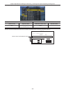
Superimposing the time code
To display the time code in the viewnder or LCD monitor during shooting or playback, set [TCG], [TCR], or [TCG/TCR] in the main menu → [VF] → [VF
INDICATOR] → [TC].
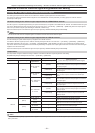
To display these time code indicators on a device connected to monitor output or the <SDI OUT1> terminal, perform the following. Set the <MON OUT
CHARACTER> switch on the side to <ON>, and set [ON] in the main menu → [I/F SETUP] → [OUTPUT SEL] → [SDI OUT1 CHAR].
To display the time code in the color bar display, set [ON] in the main menu → [VF] → [VF INDICATOR] → [TC ON COLOR BAR].
Setting the camera ID
Set the camera ID in the main menu → [CAMERA] → [CAMERA ID]. Alphanumerics, symbols, and spaces within ten characters can be used.


Find Your Products By Category
Please Login
