
0
Owner's of the Panasonic Camcorder Memory Card Camera-Recorder gave it a score of 0 out of 5. Here's how the scores stacked up:
– 15 –
Chapter 2 Description of Parts — Power supply and accessory mounting section
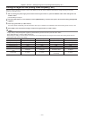
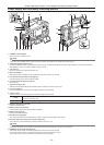
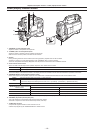
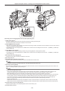
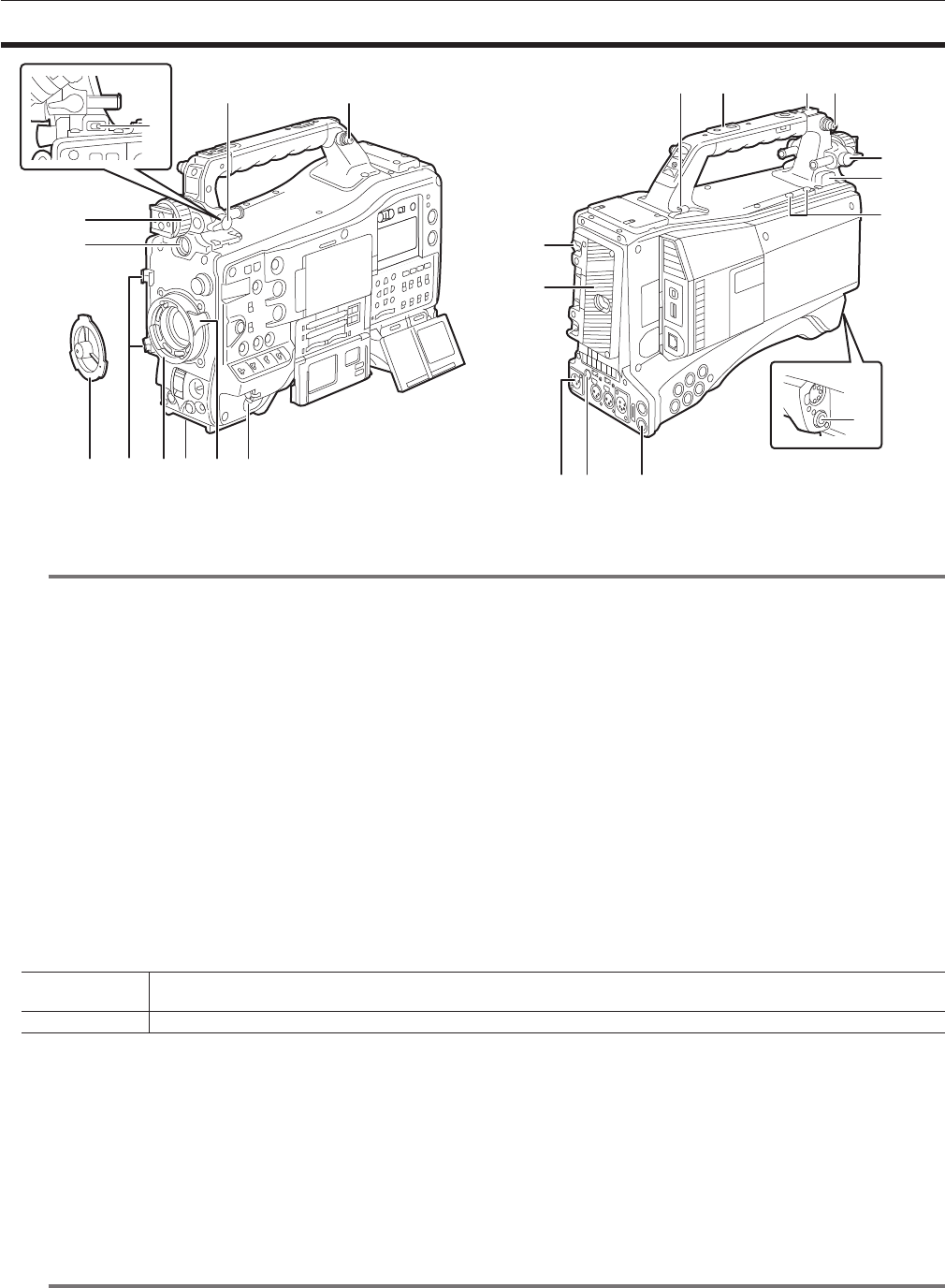
Power supply and accessory mounting section
4 5 6 7 8 1
13
12
14 15
22
17 18 10
20
21
3
9
10
2
16
19
11
19
1 <POWER> switch (page 35)
Switch used to turn on/off the power.
@@
NOTE
t Even when the <POWER> switch is set to the <OFF> position, the camera is not shut off from the main power.
2 Viewnder left/right positioning ring
To adjust the left/right position of the viewnder, loosen this ring, and slide the viewnder to the left or right to adjust it to an easy-to-view position.
After adjustment, turn in the <LOCK> direction and rmly clamp.
3 <VF> terminal
Mount the viewnder AJ-HVF21KG (optional), etc.
4 Mount cap (page 97)
Raise the lens lever to remove the cap. Replace the cap when the lens is not mounted.
5 Lens cable/microphone cable clamp (page 97)
Used for securing the lens and microphone cables.
6 Lens mount (2/3-type bayonet) (page 97)
Mount the lens.
7 Tripod mount (page 104)
Attach the optional tripod adaptor (SHAN-TM700) when mounting the camera on the tripod.
8 Lens lever (page 97)
After mounting the lens to the lens mount, tighten the lever to secure the lens.
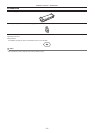
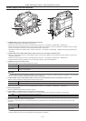
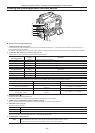
9 <LIGHT> switch
Select how to turn on/off the video light connected to the light output terminal.
<AUTO>
When the video light is left turned on, the light is illuminated at the same time that recording starts on the camera and goes out at the
same time that recording stops.
<MANUAL> The light is illuminated according to whether the video light is turned on/off.
10 Shoulder strap ttings (page 104)
Attach the shoulder strap.
11 Battery release lever (page 94)
Pull this battery release lever down to release the battery.
12 Battery holder (page 94)
Mount the Anton/Bauer battery.
13 <DC IN> terminal (page 95)
This is the input terminal for the external power supply. Connect to the external DC power supply.
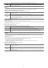
14 <DC OUT> (DC power supply) output terminal (page 106)
This is the DC12 V output terminal. It provides a maximum current of 1.5 A.
@@
NOTE
t Make sure that polarity is correct before connecting an external device. Doing so may result in a malfunction.
15 <REMOTE> terminal (page 188) (page 187)
Connect the remote control unit AJ-RC10G (optional) to remote-control some functions.
Connect the extension control unit AG-EC4G (optional) to remote-control some functions.
The remote control function is scheduled to be supported in future upgrades.


Find Your Products By Category
Please Login
