
0
Owner's of the Panasonic Camcorder Memory Card Camera-Recorder gave it a score of 0 out of 5. Here's how the scores stacked up:
– 25 –
Chapter 2 Description of Parts — Time code section
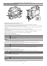
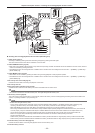
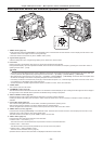
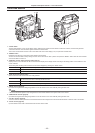
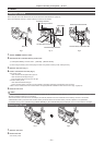
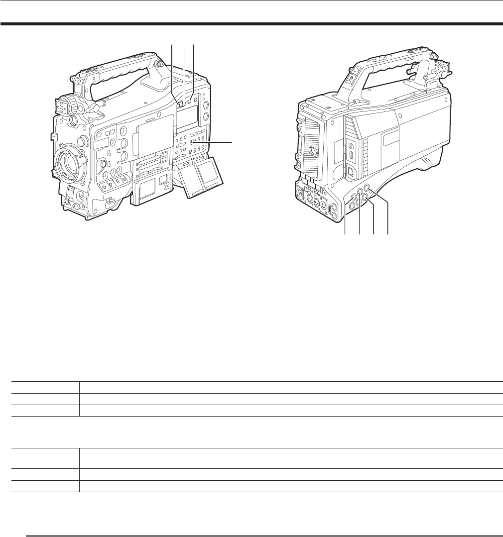
Time code section
1 3
4
2
7 865
1 <HOLD> button
The time data indication on the counter display area is retained for the duration that this button is held down. However, the time code generator
continues to advance. Press the button again to release the retained state.
This function is used to learn the time code or time data of the time counter display (CTL) of a particular recorded scene.
2 <RESET> button
Resets the time data (CTL) of the time counter display to [00:00:00:00].
To return the real time data to factory settings, set the <TCG> switch to the <SET> position and press the <RESET> button. Both the time code data
and user bits data are reset to 0.
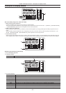
3 <DISPLAY> (counter display selector) switch (page 27)
Displays the CTL, time code and user bits in the time counter display of the display window according to the setting position of the <DISPLAY> and
<TCG> switches.
The shooting date, shooting time and time zone can also be displayed by pressing the <HOLD> button.
<UB> Displays the users bits, shooting date, shooting time, and time zone.
<TC> Displays the time code.
<CTL> Displays CTL.
4 <TCG> (time code selector) switch
Sets the advance mode for the built-in time code generator.
<F-RUN>
Used to advance the time code continuously, regardless of the P2 card recording operation. Set to this position to, for example, set the
time code to the current time or externally lock the time code.
<SET> Used to set the time code or user bits.
<R-RUN> Used to advance the time code only during recording. Records continuously time codes on P2 cards that have been spliced together.
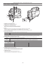
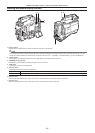
5 <SDI IN> terminal (page 65)
Input reference signals when setting the generator lock on the camera unit or when externally locking the time code.
@@
NOTE
t Be sure to set the SDI signals to input to signals of the same format selected in the system mode on the camera.
6 <GENLOCK IN> terminal (page 65)
Input reference signals when setting the generator lock on the camera unit or when externally locking the time code.
7 <TC OUT> terminal (page 65)
Connect to the time code input terminal of the external device when locking the time code of the external device to the time code on the camera.
8 <TC IN> terminal (page 65)
Input the reference time code to this terminal when the time code is locked.


Find Your Products By Category
Please Login
