
0
Owner's of the Panasonic Camcorder Memory Card Camera-Recorder gave it a score of 0 out of 5. Here's how the scores stacked up:
– 61 –
Chapter 4 Adjustments and Settings for Recording — Selection of external reference signal and generator lock setting
Selection of external reference signal and generator lock setting
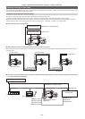
Locking the video signal to the external reference signal
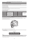
The video signal output from the camera can be locked to the reference signal supplied from an external source.
The camera can receive the external reference signal from the <GENLOCK IN> terminal (exclusively for analog signal) and <SDI IN> terminal
(exclusively for SDI signal).
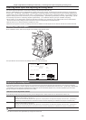
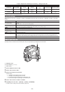
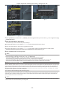
Generator-locking to the reference signal supplied from the <GENLOCK IN> terminal
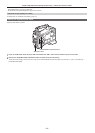
The HD-Y signal or a composite signal matching the system frame frequency is supplied to the <GENLOCK IN> terminal. To enable the reference signal
input to the <GENLOCK IN> terminal, [GL IN] must be set in the main menu → [I/F SETUP] → [GENLOCK] → [GENLOCK]. Select the output signal to
lock to the input reference signal at [GL PHASE] (at 1080/59.94i, 1080/50i only).
Adjust the horizontal phase of the reference signal and output signal at [H PHASE COARSE] and [H PHASE FINE].
@@
NOTE
t The sub-carrier of the camera’s composite signal is not locked to the sub-carrier of the reference signal.
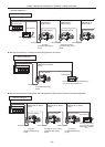
Generator-locking to the reference signal supplied from the <SDI IN> terminal
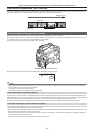
The SDI matching the system frame frequency is supplied to the <SDI IN> terminal.
To enable the reference signal input to the <SDI IN> terminal, [SDI IN] must be set in the main menu → [I/F SETUP] → [GENLOCK] → [GENLOCK].
When [SDI] is selected in the main menu → [SYSTEM] → [SYSTEM MODE] → [REC SIGNAL], the signal is synchronized with the reference signal
input to the <SDI IN> terminal regardless of the selection of [GENLOCK]. The phase of the output signal at this time is the same as the reference signal
supplied to the <SDI IN> terminal.
Adjust the horizontal phase of the reference signal and output signal at [H PHASE COARSE] and [H PHASE FINE].
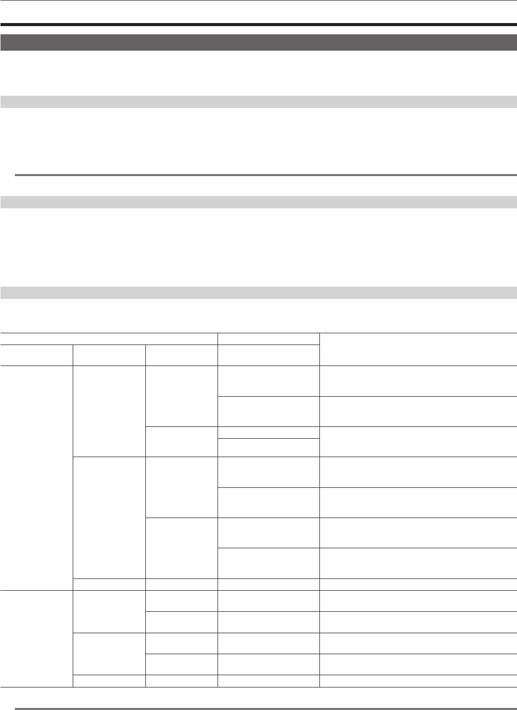
Output status
The output status changes as follows according to selection of the external reference signal and generator lock setting.
Set [GENLOCK] and [GL PHASE] in the main menu → [I/F SETUP] → [GENLOCK].
Selection of external reference signal Generator lock setting
Output signal status
(phase relationship with external reference signal)
System mode [GENLOCK]
Input signal and
input terminal
[GL PHASE]
1080i/1080P
[SDI IN]
HD SDI: <SDI IN>
terminal
[HD SDI]
HD SDI output matches the HD SDI input signal.
Down converter output has a delay of approx. 90 H from the
HD SDI input signal.
[COMPOSITE]
Down converter output matches the HD SDI input signal.
HD SDI output has an advance of approx. 90 H from the HD
SDI input signal.
SD SDI: <SDI IN>
terminal
[HD SDI] HD SDI output is not locked to the SD SDI input signal.
Down converter output is not locked to the SD SDI input
signal.
[COMPOSITE]
[GL IN]
HD-Y: <GENLOCK
IN> terminal
[HD SDI]
HD SDI output matches the HD-Y input signal.
Down converter output has a delay of approx. 90 H from the
HD-Y input signal.
[COMPOSITE]
Down converter output matches the HD-Y input signal.
HD SDI output has an advance of approx. 90 H from the
HD-Y input signal.
VBS: <GENLOCK
IN> terminal
[HD SDI]
HD SDI output matches the VBS input signal.
Down converter output has a delay of approx. 90 H from the
VBS input signal.
[COMPOSITE]
Down converter output matches the VBS input signal.
HD SDI output has an advance of approx. 90 H from the
VBS input signal.
[INT] — — Output is non-synchronous to the input signal.
480i/576i
[SDI IN]
SD SDI: <SDI IN>
terminal
—
SD SDI output matches the SD SDI input signal.
VBS output matches the SD SDI input signal.
HD SDI: <SDI IN>
terminal
—
SD SDI output is not locked to the HD SDI input signal.
VBS output is not locked to the HD SDI input signal.
[GL IN]
VBS: <GENLOCK
IN> terminal
—
SD SDI output matches the VBS input signal.
VBS output matches the VBS input signal.
HD-Y: <GENLOCK
IN> terminal
—
SD SDI output is not locked to the HD-Y input signal.
VBS output is not locked to the HD-Y input signal.
[INT] — — Output is non-synchronous to the input signal.
@@
NOTE
t In the system mode of [1080P], a generator lock is applied to the video signal when the HD-Y or HD SDI signal is input. In this case, time code may
shift by one frame.


Find Your Products By Category
Please Login
