

0
Owner's of the Kramer Electronics TV Cables Kramer Electronics TV Cables gave it a score of 0 out of 5. Here's how the scores stacked up:


KRAMER: SIMPLE CREATIVE TECHNOLOGY
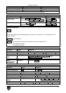
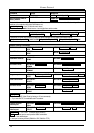
Kramer Protocol
50
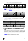
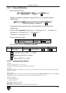
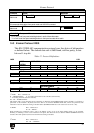
NOTE 13 - This is a request to identify the switcher/s in the system. If the OUTPUT is set as 0, and the INPUT is set as 1, 2,
5 or 7, the machine will send its name. The reply is the decimal value of the INPUT and OUTPUT. For example, for a 2216,
the reply to the request to send the audio machine name would be (HEX codes):
7D 96 90 81 (i.e. 128dec+ 22dec for 2nd byte, and 128dec+ 16dec for 3rd byte).
If the request for identification is sent with the INPUT set as 3 or 4, the appropriate machine will send its software version
number. Again, the reply would be the decimal value of the INPUT and OUTPUT - the INPUT representing the number in
front of the decimal point, and the OUTPUT representing the number after it. For example, for version 3.5, the reply to the
request to send the version number would be (HEX codes):
7D 83 85 81 (i.e. 128dec+ 3dec for 2nd byte, 128dec+ 5dec for 3rd byte).
If the OUTPUT is set as 1, then the ASCII coding of the lettering following the machine’s name is sent. For example, for the
VS-7588YC, the reply to the request to send the first suffix would be (HEX codes):
7D D9 C3 81 (i.e. 128dec+ ASCII for “Y”; 128dec+ ASCII for “C”).
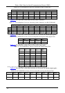
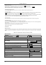
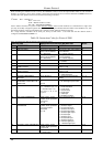
NOTE 14 - The number of inputs and outputs refers to the specific machine which is being addressed, not to the system. For
example, if six 16X16 matrices are configured to make a 48X32 system (48 inputs, 32 outputs), the reply to the HEX code
3E 82 81 82 (ie. request the number of outputs)
would be HEX codes
7E 82 90 82
ie. 16 outputs
NOTE 16 - The reply to the “REQUEST WHETHER PANEL IS LOCKED” is as in NOTE 4 above, except that here the
OUTPUT is assigned with the value 0 if the panel is unlocked, or 1 if it is locked.
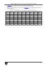
NOTE 19 – After this instruction is sent, the unit will respond to the ASCII command set defined by the OUTPUT byte. The
ASCII command to operate with the HEX command set must be sent in order to return to working with HEX codes.
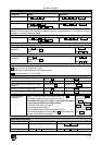
NOTE 24 – Further information needed in instructions 22 and 25, is sent using instruction 42 – which is sent prior to the
instruction. For example, to request the audio gain value of output # 9, send hex codes
2A 81 80 81
and then send HEX codes
19 89 81 81.
To set input gain change mode, send hex codes
2A 80 80 81
and then send HEX codes
16
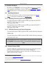
NOTE 25 – For units which detect the validity of the video inputs, Instruction 16 will be sent whenever the unit detects a
change in the state of an input (in real-time).
For example, if input 3 is detected as invalid, the unit will send the HEX codes
10 83 84 81
If input 7 is detected as valid, then the unit will send HEX codes
10 87 85 81.


Find Your Products By Category
Please Login
