
0
Owner's of the Kramer Electronics TV Cables Kramer Electronics TV Cables gave it a score of 0 out of 5. Here's how the scores stacked up:
Kramer Protocol
47
47
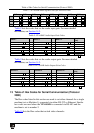
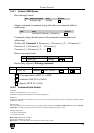
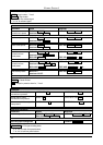
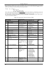
Advanced switching commands
Command
Syntax
Response
Set audio follow
video mode
AFV AFV-MODE
AFV AFV-MODE RESULT
Note:
This command effect device front-panel mode and AUD\VID command.
Read audio follow
video mode
AFV?
AFV AFV-MODE
AFV-MODE = Front panel AFV mode
"0" or "afv" to set front panel switching buttons in audio-follow-video state.
"1" or "brk" to set front panel switching buttons in their previous state when audio.
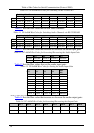
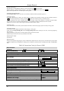
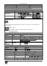
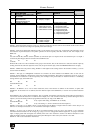
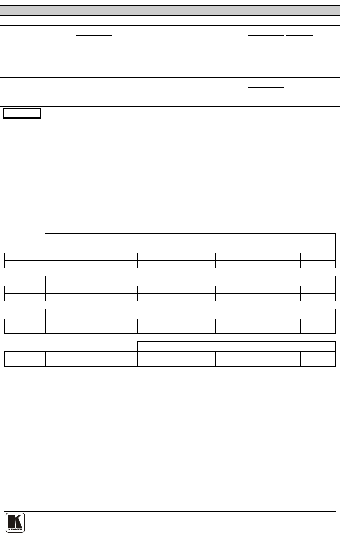
14.3 Kramer Protocol 2000
This RS-232/RS-485 communication protocol uses four bytes of information
as defined below. The default data rate is 9600 baud, with no parity, 8 data
bits and 1 stop bit.
Table 17: Protocol Definitions
MSB
LSB
DESTI-
NATION
INSTRUCTION
0
D
N5
N4
N3
N2
N1
N0
7
6
5
4
3
2
1
0
1st byte
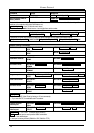
INPUT
1
I6
I5
I4
I3
I2
I1
I0
7
6
5
4
3
2
1
0
2nd byte
OUTPUT
1
O6
O5
O4
O3
O2
O1
O0
7
6
5
4
3
2
1
0
3rd byte
MACHINE NUMBER
1
OVR
X
M4
M3
M2
M1
M0
7
6
5
4
3
2
1
0
4th byte
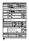
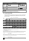
1
st
BYTE: Bit 7 – Defined as 0.
D – “DESTINATION”: 0 - for sending information to the switchers (from the PC);
1 - for sending to the PC (from the switcher).
N5…N0 – “INSTRUCTION”
The function that is to be performed by the switcher(s) is defined by the INSTRUCTION (6 bits). Similarly, if a function is
performed via the machine’s keyboard, then these bits are set with the INSTRUCTION NO., which was performed. The
instruction codes are defined according to the table below (INSTRUCTION NO. is the value to be set for N5…N0).
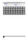
2
nd
BYTE: Bit 7 – Defined as 1.
I6…I0 – “INPUT”.
When switching (ie. instruction codes 1 and 2), the INPUT (7 bits) is set as the input number which is to be switched.
Similarly, if switching is done via the machine’s front-panel, then these bits are set with the INPUT NUMBER which was
switched. For other operations, these bits are defined according to the table.
3
rd
BYTE: Bit 7 – Defined as 1.
O6…O0 – “OUTPUT”.


Find Your Products By Category
Please Login
