
0
Owner's of the Kramer Electronics TV Cables Kramer Electronics TV Cables gave it a score of 0 out of 5. Here's how the scores stacked up:

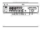
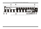
Your VP-4x8AK 4x8 VGA / UXGA / Audio Matrix Switcher
7
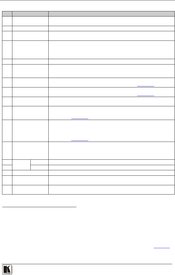
Table 2: Front Panel VP-4x8AK 4x8 VGA / UXGA / Audio Matrix Switcher Features
#
Feature
Function
1 IR Receiver The yellow LED is illuminated when receiving signals from the infrared
remote control transmitter
2 POWER LED The green LED is illuminated when the unit is turned ON
3 SELECTOR OUT
Buttons
Select the output
1
4
to which the input is switched
SELECTOR IN
Buttons
Select the input (from 1 to 4) to switch to the output (after selecting an
output).
When a signal is detected at an input connector, the corresponding input
button is illuminated
5 ALL Button Pressing ALL followed by an INPUT button, connects that input to all outputs
2
6
OFF Button Press an OUT SELECTOR button and then an OFF button to disconnect that
output from the inputs.
Press the ALL button and then the OFF button to disconnect all the outputs
7 VIDEO Button When pressed
3
6.7
actions relate to video. Press the VIDEO button together with
the AUDIO button to set the Switching delay time (see Section )
8 AUDIO Button When pressed
4
6.7
actions relate to audio. Press the VIDEO button together with
the AUDIO button to set the Switching delay time (see Section )
9 AFV Button When pressed, the audio channels follow the video channels. The button is
illuminated when the AFV mode is selected
10 STO (Store) Button Pressing STO followed by an input/output button stores the current setting
5
6.8
Press the RCL button together with the STO button to set the machine
number (see Section )
11 RCL (Recall) Button Pressing the RCL button and the corresponding IN/OUT button recalls a setup
from the non-volatile memory.
Press the RCL button again to implement the new status
Press the RCL button together with the STO button to set the machine
number (see Section
6.8)
12 TAKE Button Pressing TAKE toggles the mode between the Confirm mode
6
13
and the
At Once mode (user confirmation per action is unnecessary). When in
Confirm mode, pressing the TAKE button will implement a pending
configuration
AUDIO
LEVEL
- Button Press to decrease the input or output audio signal level
14 + Button Press to increase the input or output audio signal level
15 LOCK Button Disengages the front panel switches
16 STATUS 7-segment
display
Displays the selected INPUT switched to the OUTPUT (marked above each
input)
7
17
REL. AUDIO LEVEL
7-segment display
Displays
8
the relative audio level
9
1 From 1 to 8
2 For example, press ALL and then Input button # 2 to connect input # 2 to all the outputs
3 The VIDEO button is illuminated when in breakaway mode and actions relate to video
4 The AUDIO button is illuminated when in breakaway mode and actions relate to audio
5 For example, press STO and then the output button # 3 to store in Setup # 3, or the input button 4 to store in Setup 12
6 When in the Confirm mode, the TAKE button illuminates
7 Also displays the number of INPUT and OUTPUT ports, the firmware version number, and the MACHINE #. Refer to Section
7.2.1
8 A dot following the number, represents a value of 0.5. For example, 3.5 displays as "3."
9 The input audio level ranges from -100dB to +20dB and the output audio level ranges from -100dB to +7.5dB


Find Your Products By Category
Please Login
