
0
Owner's of the Kramer Electronics TV Cables Kramer Electronics TV Cables gave it a score of 0 out of 5. Here's how the scores stacked up:

Kramer Protocol
49
49
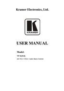
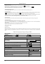
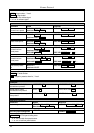
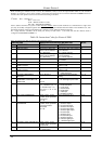
INSTRUCTION DEFINITION FOR SPECIFIC INSTRUCTION NOTE
#
DESCRIPTION
INPUT
OUTPUT
31 REQUEST WHETHER PANEL
IS LOCKED
0 0 16
42 AUDIO PARAMETER
SETTINGS FOR
INSTRUCTIONS 22, 25
INPUT Bit:
I0 - 0=input; 1=output
24
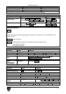
56
CHANGE TO ASCII
0
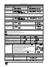
Kramer protocol 3000
19
61 IDENTIFY MACHINE 1 - video machine name
2 - audio machine name
3 - video software version
4 - audio software version
0 - Request first 4 digits
1 - Request first suffix
2 - Request second suffix
3 - Request third suffix
10 - Request first prefix
11 - Request second prefix
12 - Request third prefix
13
62
DEFINE MACHINE
1 - number of inputs
2 - number of outputs
3 - number of setups
1 - for video
2 - for audio
14
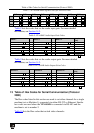
NOTES on the above table:
NOTE 1 - When the master switcher is reset, (e.g. when it is turned on), the reset code is sent to the PC. If this code is sent to
the switchers, it will reset according to the present power-down settings.
NOTE 2 - These are bi-directional definitions. That is, if the switcher receives the code, it will perform the instruction; and if
the instruction is performed (due to a keystroke operation on the front panel), then these codes are sent. For example, if the
HEX code
01 85 88 83
was sent from the PC, then the switcher (machine 3) will switch input 5 to output 8. If the user switched input 1 to output 7
via the front panel keypad, then the switcher will send HEX codes:
41 81 87 83
to the PC.
When the PC sends one of the commands in this group to the switcher, then, if the instruction is valid, the switcher replies by
sending to the PC the same four bytes that it was sent (except for the first byte, where the DESTINATION bit is set high).
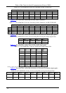
NOTE 3 - SETUP # 0 is the present setting. SETUP # 1 and higher are the settings saved in the switcher's memory, (i.e. those
used for Store and Recall).
NOTE 4 - The reply to a "REQUEST" instruction is as follows: the same instruction and INPUT codes as were sent are
returned, and the OUTPUT is assigned the value of the requested parameter. The replies to instructions 10 and 11 are as per
the definitions in instructions 7 and 8 respectively. For example, if the present status of machine number 5 is breakaway
setting, then the reply to the HEX code
0B 80 80 85
would be HEX codes
4B 80 81 85
NOTE 6 – If INPUT is set to 127 for these instructions, then, if the function is defined on this machine, it replies with
OUTPUT=1. If the function is not defined, then the machine replies with OUTPUT=0, or with an error (invalid instruction
code).
If the INPUT is set to 126 for these instructions, then, if possible, the machine will return the current setting of this function,
even for the case that the function is not defined. For example, for a video switcher which always switches during the VIS of
input #1, (and its VIS setting cannot be programmed otherwise), the reply to the HEX code
0A FE 80 81 (ie. request VIS setting, with INPUT set as 126dec)
would be HEX codes
4A FE 81 81 (ie. VIS setting = 1, which is defined as VIS from input #1).
NOTE 8 - The reply is as in TYPE 3 above, except that here the OUTPUT is assigned with the value 0 if the setup is not
defined / no valid input is detected; or 1 if it is defined / valid input is detected.
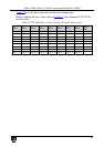
NOTE 9 - An error code is returned to the PC if an invalid instruction code was sent to the switcher, or if a parameter
associated with the instruction is out of range (e.g. trying to save to a setup greater than the highest one, or trying to switch an
input or output greater than the highest one defined). This code is also returned to the PC if an RS-232 instruction is sent
while the machine is being programmed via the front panel. Reception of this code by the switcher is not valid.
NOTE 10 – This code is reserved for internal use.


Find Your Products By Category
Please Login
