
0
Owner's of the CHIEF TV Mount CHIEF TV Mount gave it a score of 0 out of 5. Here's how the scores stacked up:


Installation Instructions WMA2S
13
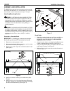
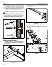
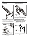
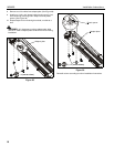
2. Secure wall bracket top covers (C) to wall bracket arms by
installing four #8-32 x 1/2" Phillips pan machine screws (T)
through holes in covers and wall bracket. (See Figure 27)
3. Place wall bracket bottom covers (D) over bottom of each
wall bracket arm. (See Figure 26)
4. Secure wall bracket bottom covers (D) to wall bracket arms
by installing four #8-32 x 1/2" Phillips pan machine screws
(T) through holes in covers and wall bracket.
(See Figure 27)
Figure 27
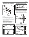
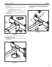
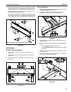
Adjustments
Bracket Width Adjustment
1. Loosen two flat head cap screws on wall bracket. (See
Figure 28)
2. Slide wall brackets to corresponding width of studs. (See
Figure 28)
3. Tighten two flat head cap screws on wall bracket. (See
Figure 28)
Figure 28
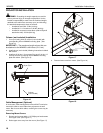
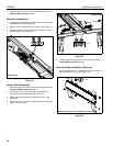
Pitch Adjustment
1. Remove mount covers from the mount following instructions
in Removing Mount Covers section.
2. Loosen two 1/4-20 x 5/8" hex head cap screws (P) on
underside of mounting bracket. (See Figure 29)
Figure 29
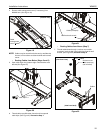
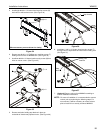
3. Loosen two bolts on either side of pitch adjustment screw.
(See Figure 30)
4. Adjust pitch adjustment screw until mount is at desired pitch
level.
• Turn clockwise to raise mounting level.
• Turn counterclockwise to lower mounting level. (See
Figure 30)
5. Tighten two bolts on either side of pitch adjustment screw.
(See Figure 30)
6. Tighten two 1/4-20 x 5/8" hex head screws (P) on underside
of mounting bracket. (See Figure 29)
Figure 30
2
(T) x 4
4
(T) x 4
(Mount accessory arm not shown for clarity)
1 3
2
2
(bottom view)
2
(P) x 2
6
3
5
or
4


Find Your Products By Category
Please Login
