
0
Owner's of the Behringer Car Amplifier EUROPOWER Amplifier with ATR gave it a score of 0 out of 5. Here's how the scores stacked up:


ENGLISH
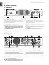
EUROPOWER EP2000/EP4000 User Manual
8
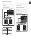
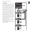
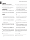
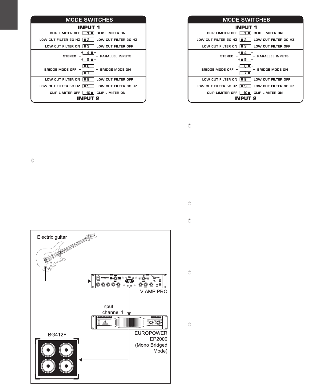
When running in mono-bridged mode, the voltage of both chan-
nels is added up and fed into a single loudspeaker system. There
is one input and one output signal respectively, and only the
controls of channel 1 (and not of channel 2) are used.
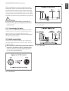
However, should the DIP switches 4 and 5 still be in
◊
PARALLEL INPUTS position while in mono-bridged mode,
the signal on the free input (input channel 2) can be
forwarded to an additional amp.
Examples:
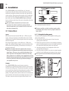
Driving a single 8-Ohm loudspeaker.•
Driving a single 4-Ohm loudspeaker.•
When the amp is overdriven for longer periods of time,
◊
the output signal may occasionally be muted for several
seconds. In certain situations, excessive overdriving may
trigger off the automated fuse. To avoid overdriving the
amp, please continually make sure that an appropriate
volume level is applied.
Caution
!
2-Ohm loads should never be applied when in
◊
mono-bridged mode.
When connecting a balanced input signal, please make sure
◊
to exclusively use balanced cables for passing the signal
further on. Otherwise, a single unbalanced cable can turn
the entire signal unbalanced.
Safety precautions for mono-bridged operation
Running your amp in mono-bridged mode can quickly
◊
result in excessive overdriving and premature shutting
down of the unit itself. In the worst-case scenario, your
loudspeakers may be damaged permanently. Therefore,
you should always make sure that the speakers you use can
indeed handle the power load fed into them.
A voltage of up to 100 V RMS is present between the output
◊
connectors of the EP4000. Always implement appropriate
safety precautions when connecting your speakers to avoid
the risk of electric shock.
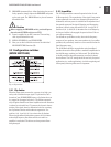
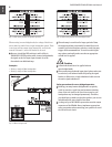
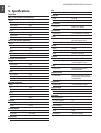
Fig. 3.4: DIP switch positions for parallel operation
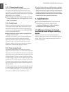
Fig. 3.5: Mono-bridged mode
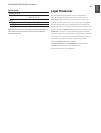
Fig. 3.6: DIP switch positions for mono-bridged mode


Find Your Products By Category
Please Login
