

0
Owner's of the Behringer Car Amplifier EUROPOWER Amplifier with ATR gave it a score of 0 out of 5. Here's how the scores stacked up:


ENGLISH
EUROPOWER EP2000/EP4000 User Manual
4
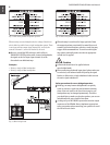
Control elements2.
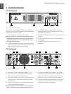
Front panel2.1
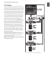
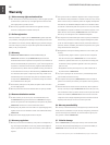
Fig. 2.1: Front panel control elements
Since control elements of both the EP2000 and the EP4000 are
identical, we have used the EP2000 as the model represented in
the illustrations to assure simplicity.
The main switch is used to power up the amp.
[1]
Merely switching the unit off does not mean that it is fully
◊
disconnected from the mains. When not using the unit for
prolonged periods of time, please unplug the unit’s power
cord from the power outlet.
Ventilation openings are located at the front of the unit, so
[2]
that hot air is prevented from being trapped inside the unit,
thus causing faulty operation or even damage.
The CLIP LED lights up when the signal is distorted.
[3]
Should distortion occur, reduce the input level, so that the
CLIP LED stops lighting up.
The SIGNAL LED lights up as long as a signal is present at
[4]
the input.
The Gain control (channels 1 and 2) is used for setting up
[5]
the input gain.
The POWER LED lights up as soon as the unit is
[6]
powered up.
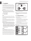
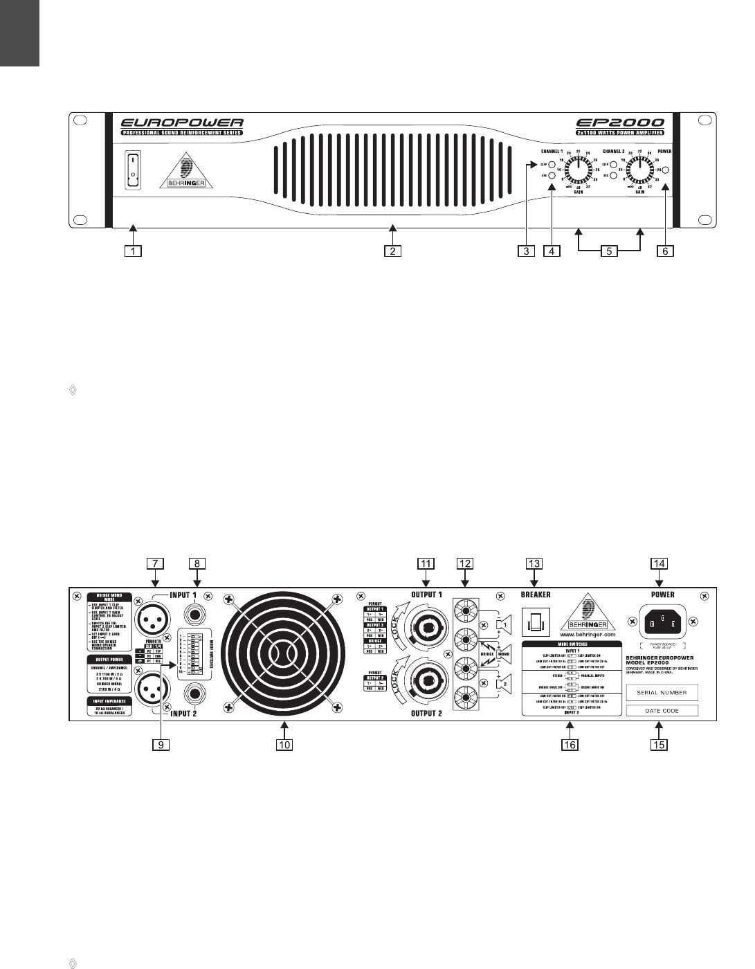
Rear panel2.2
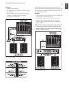
Fig. 2.2: Rear panel control elements
These are the balanced XLR inputs (channels 1 and 2).
[7]
These are the stereo ¼" TRS inputs (channels 1 and 2).
[8]
They can also be used with unbalanced plugs.
These are the MODE switches, used to alter the operating
[9]
modes as well as to set the limiters and high-pass lters
(see chapter 2.3).
The unit’s fan is located here. Fan speed adjusts automati-
[10]
cally to assure trouble-free operation.
To prevent faulty operation, please assure that the unit is
◊
kept at a distance from other appliances emanating heat.
These are the speaker outputs (channels 1 and 2). When
[11]
running the unit in mono-bridged mode (see chapter 2.3.5),
please use the channel 1 output exclusively. For further
information on the connectors please refer to chapter 4.1.
These are the output terminals (channels 1 and 2). When
[12]
running in mono, please make sure to use both middle
connectors to connect your loudspeaker.


Find Your Products By Category
Please Login
