
0
Owner's of the Behringer Car Amplifier EUROPOWER Amplifier with ATR gave it a score of 0 out of 5. Here's how the scores stacked up:


ENGLISH
EUROPOWER EP2000/EP4000 User Manual
5
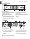
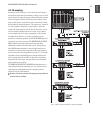
BREAKER (automated fuse). After eliminating the cause of
[13]
faulty operation, simply depress the BREAKER and power
up the unit again. The BREAKER acts in place of common
discardable fuses.
Caution
!
Before engaging the BREAKER switch, you should power
◊
down the unit (POWER switch set to OFF)!
Power is supplied via an IEC connector. The matching
[14]
cable is provided with the unit.
SERIAL NUMBER of your EUROPOWER.
[15]
Here you can nd a detailed overview of the individual
[16]
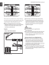
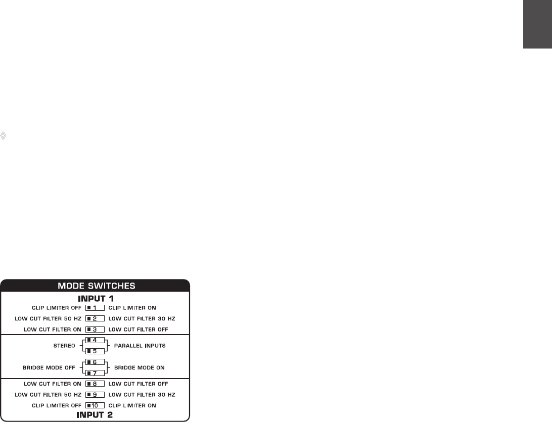
MODE SWITCHES functions (
{9}
).
Configuration switches 2.3
(MODE SWITCHES)
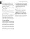
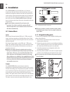
Clip limiter2.3.1
When the input signal connected to your amp is too high, you
end up with a distorted output signal. To prevent this, both
channels of your EUROPOWER feature a clip limiter that can
be engaged or disengaged selectively. The limiters automati-
cally recognize distortion and lower amplication until distortion
is reduced to a tolerable level. To preserve the dynamic charac-
teristics of the signal when low distortion levels are occurring,
the clip limiters function with moderate suppression. Use
switches 1 (ch. 1) and 10 (ch. 2) to activate the clip limiters.
When using broadband loudspeaker systems, the clip limiter
reduces high frequency distortions which occur when an
amplier is overloaded. The drivers are thus protected from
being damaged.
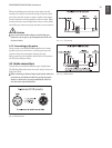
Input filter2.3.2
The LF (high-pass) lter removes frequencies below 30 and
50 Hz respectively. The reproduction of the signal’s bass portion
is thus optimized, since ultra-low, distracting frequencies are
eliminated, and more power is available for the reproduction of
the wanted segment of the signal. Engaging and disengaging
the lters is done by using the switches 3 (ch. 1) and 8 (ch. 2).
Switches 2 (ch. 1) and 9 (ch. 2) determine the cut-off frequency.
As long as the lter is disengaged, frequencies below 5 Hz are
cut to prevent damage.
You should set up the lters so they best suit the frequency
response of your speakers, since some speakers (e.g. bass reex
speakers) are particularly sensitive to over-excursion below the
listed frequency range.
The 50 Hz lter should be engaged when using broadband
speakers because the lter provides a moderate amplication in
the 100-Hz range, resulting in a fuller sound. The 30 Hz lter
is ideally suited for subwoofer operation as well as for broad-
band cabinets. The “Off” setting should be used only for special
applications (e.g. studio applications), in which recognizing and
subsequently removing infra-sound is important.
Fig. 2.3: Dip-switches


Find Your Products By Category
Please Login
