

0
Owner's of the Behringer Car Amplifier EUROPOWER Amplifier with ATR gave it a score of 0 out of 5. Here's how the scores stacked up:


ENGLISH
EUROPOWER EP2000/EP4000 User Manual
10
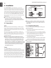
Installation4.
Your EUROPOWER can be installed into a 19" rack and
requires two rack units. Please use four attaching screws and
washers for installation. Reinforce the back end, especially for
on-the-road use. Please assure that enough cool air reaches the
rack, especially when other rack equipment emanates a lot of
heat. In the case of the EUROPOWER EP2000 and EP4000,
hot air circulates at the front of the unit to thermally relieve the
rack enclosure.
Fan speed adjusts automatically and assures safe
◊
operation. Never block ventilation openings. Should
internal temperature reach extreme values, the unit will
shut down automatically.
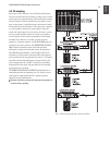
Connections4.1
Inputs
Each channel features balanced XLR and ¼" TRS stereo jack
inputs, with input impedances of 20 kΩ (balanced) and 10 kΩ
(unbalanced). In general, balanced signals cause less noise than
unbalanced signals.
For balanced input signals, use the XLR and ¼" TRS stereo
inputs. For unbalanced input signals, use the unused pin of the
XLR connector with grounding. No alteration is necessary on
mono jack connectors.
Should you register distractive signals such as noise or
◊
hissing, we recommend separating the amp input from the
signal source. This way, you can quickly determine if the
noise originates in the equipment connected to the amp.
Always make sure to completely lower amplication of both
channels before powering up the amp (GAIN control turned
all the way leftward). Otherwise, permanent damage to
your speakers may occur.
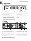
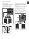
Outputs
Your EUROPOWER offers several output connection
possibilities: two professional speaker connectors and two pairs
of touch-safe binding posts. The professional speaker connectors
were especially developed for driving high-power speakers. They
snap in securely, prevent electric shock and assure correct
polarity. The upper connector drives either one or both channels,
and is therefore well-suited for mono-bridged operation (1+/2+).
The lower connector carries the signals from channel 2 only.
Whenever possible, use thick and short speaker cables
◊
to minimize power losses. Never lay output cables near
input cables.
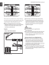
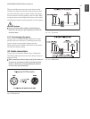
Using the binding posts4.1.1
To connect the loudspeakers to the amplier’s binding posts,
please do the following:
Switch off the amp and disconnect it from the mains 1)
(unplug mains connector).
Remove the protective plastic covers shielding the binding 2)
posts by loosening the two screws on the right-hand side of
the connections and lift the plastic cover upwards.
Attach the terminal of your loudspeaker cable to the 3)
corresponding binding post.
Place the protective plastic covers into its original upright 4)
position on each binding post and replace the two screws.
Never operate the device without the protective plastic
◊
covers in place!
Fig. 4.1: Professional speaker connectors
Fig. 4.2: Protective plastic covers shielding the binding posts


Find Your Products By Category
Please Login
