
0
Owner's of the Samson Car Amplifier Samson Car Amplifier gave it a score of 0 out of 5. Here's how the scores stacked up:


7
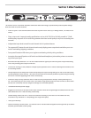
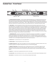
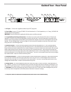
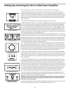
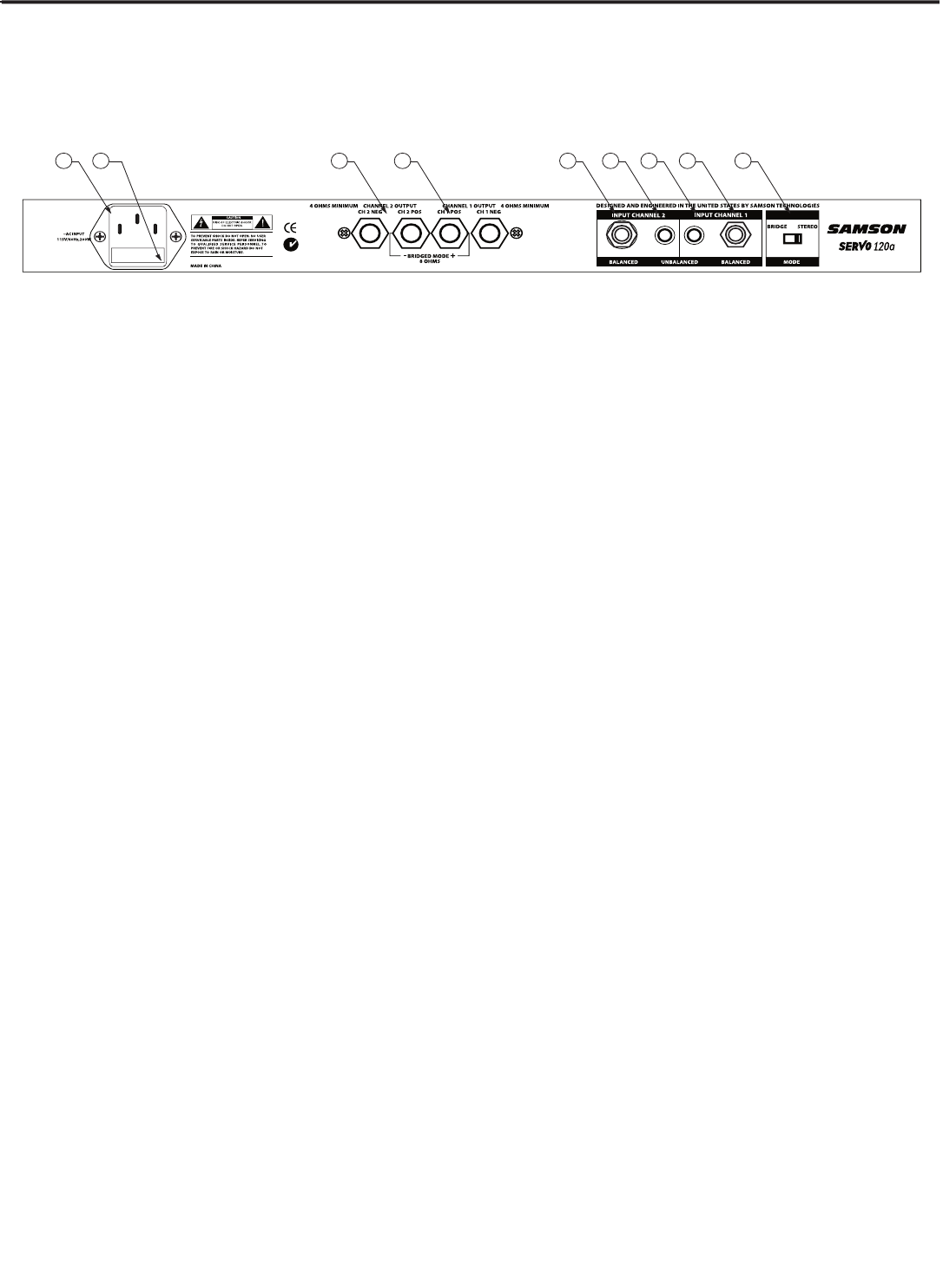
Guided Tour - Rear Panel
1: AC Input
- Connect the supplied standard 3-pin “IEC” plug here.
2: Fuse
Holder
- Insert a 2.5 amp, SLO-BLO 125 volt fuse here for 115 volt operation, or a 1.5 amp, SLO-BLO 250
volt fuse for 230 volt operation.
WARNING:
Fuses should only be replaced with the power cord disconnected.
3: 5-way Binding Post Output Connectors
- Use these to connect each channel of the Servo 120a to loud-
speakers. Be sure to connect the loudspeaker correctly, with the red (+) terminal normally connected to the
positive input of the speaker and the black (ground) terminal normally connected to the negative input of the
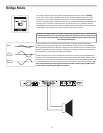
speaker. See the “Bridge Mode” section on page 10 in this manual for speaker connection instructions when
using the Servo 120a in Bridge mode.
4: Balanced Inputs*
- Connect incoming signal to these electronically balanced 1/4" TRS (Tip/Ring/Sleeve)
jacks, wired as follows: Tip hot, Ring cold, and Sleeve ground. Use balanced three-conductor cabling and TRS
plugs wherever possible (unbalanced two-conductor plugs can also be inserted into these inputs, but you’ll get
better signal quality and less outside noise and hum if you use balanced lines). Stereo signals should be con-
nected to both the left and right input jacks; when operating the Servo 120a in Bridge mode, use the left input
jack only (see page 10 in this manual for more information). The Servo 120a accepts input levels of any strength
but needs at least +4 dBu to achieve maximum power.
5: Unbalanced Inputs*
- Connect incoming signal to these unbalanced RCA-type jacks. Stereo signals should
be connected to both the left and right input jacks; when using the Servo 120a in Bridge mode, use the left
input jack only (see page 10 in this manual for more information). The Servo 120a accepts input levels of any
strength but needs at least -10 dBv to achieve maximum power.
6: Bridge switch
- For normal operation, place this switch at its right (“STEREO”) position. When placed at its
left (“BRIDGE”) position, the two amplifier sections (the left and right channels) are bridged, providing full 120
watt power into a single output. For more information, see the “Bridge Mode” section on page 10 in this manu-
al.
WARNING:
Due to the extremely high power output of the Servo 120a when used in Bridge mode, be sure
to use only 8 ohm loudspeakers sufficiently rated to handle the resultant wattage.
* If required, both the balanced and unbalanced inputs can be used simultaneously.


Find Your Products By Category
Please Login
