
0
Owner's of the Samson Car Amplifier Samson Car Amplifier gave it a score of 0 out of 5. Here's how the scores stacked up:
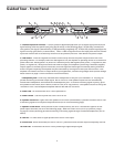
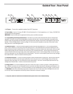
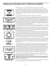


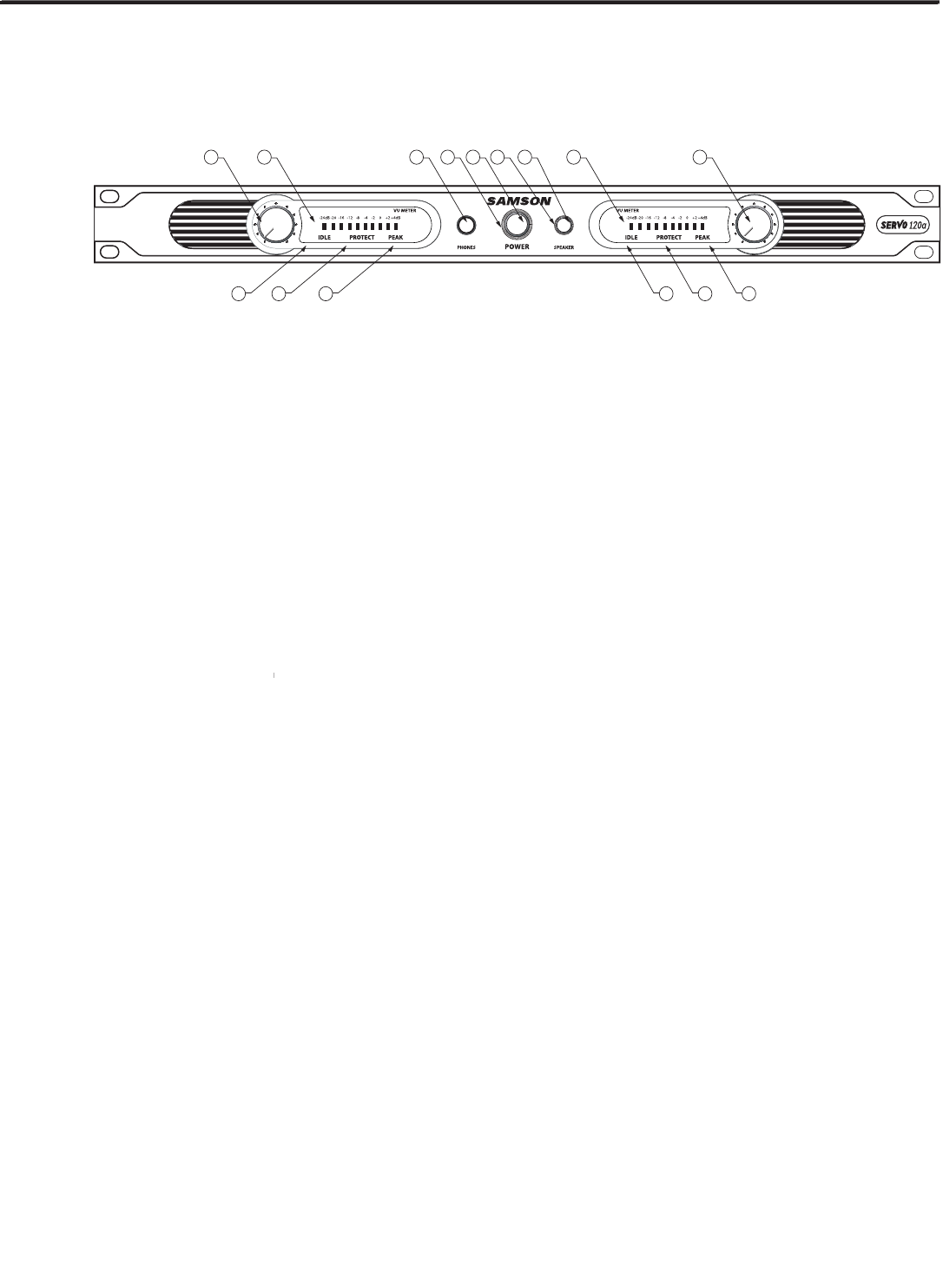
Guided Tour - Front Panel
1: Channel input level controls
- These 41-position detented knobs allow you to adjust the input level of the
signal arriving at the rear-panel input jacks (see #4 and #5 on the following page). At their fully counterclock-
wise position, the signal is attenuated by 70 dB (essentially completely off). At their fully clockwise position, the
signal is at unity gain (that is, no attenuation). When +4 dBu of signal arrives at the input jacks and the Channel
input level controls are set to their fully clockwise “0 dB” position, the Servo 120a delivers full power output.
2: LED meters
-
These ten-segment LED meters continuously monitor the power output level for the corre-
sponding channel. For example, when the -8dB segment is lit, the amplifier is operating at 20% of it's maximum
power. When the -4dB segment is lit, 40% of it's maximim power, 0dB segment, 60% power, +2 segment lit, 80%
power, +4 segment lit, 100% power. When the PEAK LED lights, the amplifier is producing a distorted (clipped)
output signal For the best signal-to-noise ratio, the PEAK segment should light occasionally during maximum
levels: If it lights frequently, the amplifier may be overloadedTry turning down the input level controls. If the
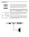
amplifier now delivers too low an output level for your application, consider using Bridge mode (see the “Bridge
Mode” section on page 10 in this manual for more inform
ation).
3: Headphone jack
-
3: Headphone jack -3: Headphone jack
Connect any standard stereo headphones to this jack (via a standard 1/4" TRS plug) for
private monitoring of the final output signal. NOTE: The Servo 120a speaker outputs are
not
automatically
muted when headphones are inserted into the Headphone jack—to monitor incoming signal in privacy, press
the Speaker on/off switch (see #7 below) so that it is out (in its “up” position)—the Speaker on/off LED will go off.
The built-in Servo 120a headphone amplifier delivers 400 mW into 100 ohms.
4: Power LED
- Lit whenever the Servo 120a is powered on.
5: Power switch
- Use this to power the Servo120 on or off.
6: Speaker on/off LED
- Lights when the Speaker on/off switch (see #6 above) is pressed in and the Servo 120a
is delivering signal to its rear panel output terminals (see #7 on the following page).
7: Speaker on/off switch
- When pressed in (the normal position), the Servo 120a delivers signal to its rear
panel output terminals (see #3 on the following page). When this switch is out (in its “up” position), outgo-
ing signal is muted, allowing personal monitoring of incoming signal through connected headphones (see #3
above).
8: Idle LED
- Lit when there is signal present at the Servo 120a's input.
9: Protect LED
- When illuminated, the Servo 120a is in protection mode and the outputs temporarily shut off.
10: Peak LED
- Lit whenever the Servo 120a is producing a clipped output signal.
6


Find Your Products By Category
Please Login
