
0
Owner's of the Kramer Electronics Weather Radio Kramer Electronics Weather Radio gave it a score of 0 out of 5. Here's how the scores stacked up:
6
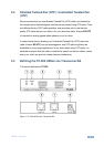
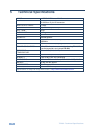
TP-202 - Overview
#
Feature
Function
1
EQ. Trimmer
Adjust the cable compensation equalization level
Insert a screwdriver into the small hole and carefully
rotate it, to trim the appropriate level
2
LEVEL Trimmer
Adjust the output signal level
3
UXGA OUT 1 15-pin HD Connector
Connect to the first UXGA acceptor
4
UXGA OUT 2 15-pin HD Connector
Connect to the second UXGA acceptor
5
ON LED
Illuminates when receiving power
6
LINE OUT RJ-45 Connector
Connect to the LINE IN connector on an additional
TP-202
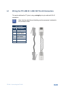
Using a UTP CAT 5 cable with RJ-45 connectors at
both ends (the PINOUT is defined in 4.1)
7
LINE IN RJ-45 Connector
Connect to the LINE OUT RJ-45 connector on the
transmitter
For example, the PT-110, as Figure 3 illustrates
8
12V DC
+12V DC connector for powering the unit
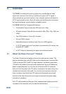
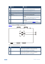
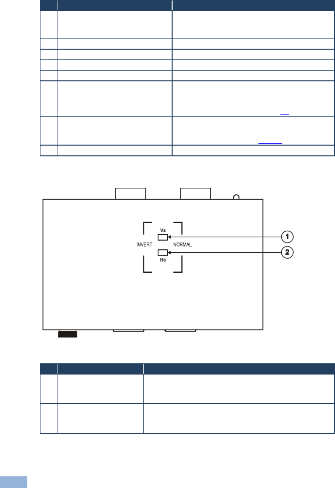
Figure 2 defines the TP-202 underside panel:
Figure 2: TP-202 (Underside Panel)
#
Feature
Function
1
VS Switch
Slide the switch to NORMAL to retain the polarity
Slide the switch to INVERT to invert the VS polarity
By default, both switches are set to NORMAL
2
HS Switch
Slide the switch to NORMAL to retain the polarity
Slide the switch to INVERT to invert the HS polarity
By default, both switches are set to NORMAL


Find Your Products By Category
Please Login
