

0
Owner's of the Kramer Electronics Weather Radio Kramer Electronics Weather Radio gave it a score of 0 out of 5. Here's how the scores stacked up:


TP-202 - Connecting the TP-202
7
4 Connecting the TP-202
Always switch off the power to each device before connecting it to your
TP-202. After connecting your TP-202, connect its power and then
switch on the power to each device.
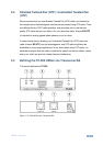
You can use the TP-202 UXGA Line Transceiver/DA to configure a UXGA DA
system. This lets you transmit a computer graphics signal to two displays via long
line CAT 5 UTP cabling.
By using two TP-202 units, you can transmit the signal to an additional TP-202.
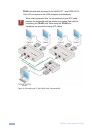
To connect the TP-202, as the example in Figure 3 illustrates, do the following:
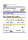
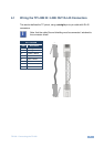
1. Connect a transmitter (for example, the Kramer PT-110 UXGA Line Transmitter)
to the LINE IN RJ-45 connector via CAT 5 cabling, see Section 4.1.
You can also connect an HD transmitter, such as the Kramer TP-219HD.
2. Set the VS and HS switches on the underside of the unit to NORMAL.
3. Connect the UXGA OUT 1 15-pin HD connector to an UXGA acceptor (for
example, display 1).
4. Connect the UXGA OUT 2 15-pin HD connector to an UXGA acceptor (for
example, display 2).
5. Check the image on the display. If it is not stable, set the VS and HS
switches to INVERT to obtain a stable image.
6. If required, connect the LINE OUT RJ-45 connector on the TP-202 to an
additional TP-202.
Up to six units may be connected with minimal deterioration. The combined length
between the first and the last unit may exceed 300 meters.
7. If required, adjust the video output signal level and/or cable compensation
equalization level.
Use a screwdriver to carefully rotate the trimmer, adjusting the appropriate level
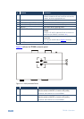
8. If necessary, set the HS and VS switches on the TP-202 underside.
By default, both switches are set to normal (see Figure 2).
9. Connect the 12V DC power adapter to the power socket and connect the
adapter to the mains electricity (not shown in Figure 3).
The signal from the UXGA source is transmitted via CAT 5 cable to the
i


Find Your Products By Category
Please Login
