
0
Owner's of the Kramer Electronics TV Cables Kramer Electronics TV Cables gave it a score of 0 out of 5. Here's how the scores stacked up:
26
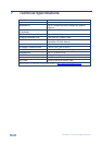
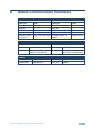
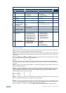
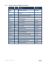
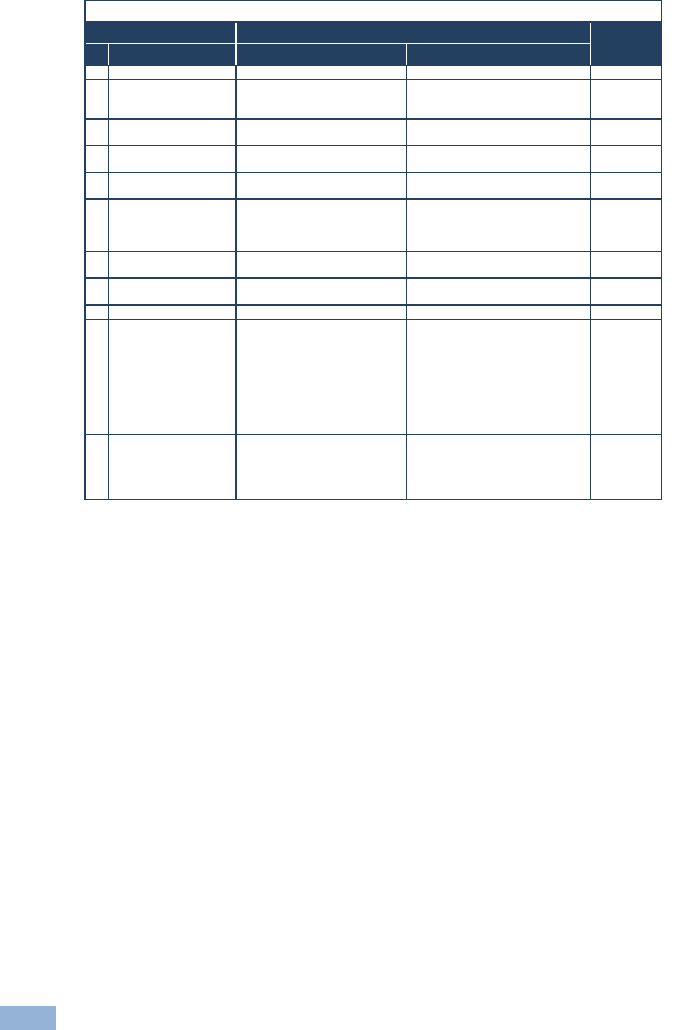
VS-66HN - Kramer Protocol 2000
Instruction Codes for Protocol 2000
Instruction
Definition for Specific Instruction
Notes
#
Description
Input
Output
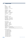
0
RESET VIDEO
0
0
1
1
SWITCH VIDEO
Set equal to video input which is
to be switched
(0 = disconnect)
Set equal to video output which is
to be switched
(0 = to all the outputs)
2, 15
3
STORE VIDEO
STATUS
Set as SETUP #
0 - to store
1 - to delete
2, 3, 15
4
RECALL VIDEO
STATUS
Set as SETUP #
0
2, 3, 15
5
REQUEST STATUS
OF A VIDEO OUTPUT
Set as SETUP #
Equal to output number whose
status is reqd
4, 3
15
REQUEST WHETHER
SETUP IS DEFINED /
VALID INPUT IS
DETECTED
SETUP #
or
Input #
0 - for checking if setup is defined
1 - for checking if input is valid
8
30
LOCK FRONT PANEL
0 - Panel unlocked
1 - Panel locked
0
2
31
REQUEST WHETHER
PANEL IS LOCKED
0
0
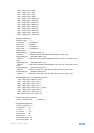
16
56
CHANGE TO ASCII
0
Kramer protocol 3000
19
61
IDENTIFY
MACHINE
1 - video machine name
2 - audio machine name
3 - video software version
4 - audio software version
5 - RS422 controller name
6 - RS422 controller version
7 - remote control name
8 - remote software version
9 - Protocol 2000 revision
0 - Request first 4 digits
1 - Request first suffix
2 - Request second suffix
3 - Request third suffix
10 - Request first prefix
11 - Request second prefix
12 - Request third prefix
13
62
DEFINE MACHINE
1 - number of inputs
2 - number of outputs
3 - number of setups
1 - for video
2 - for audio
3 - for SDI
4 - for remote panel
5 - for RS-422 controller
14
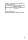
NOTES on the above table:
NOTE 1 - When the master switcher is reset, (e.g. when it is turned on), the reset code is sent to the PC. If this code is
sent to the switchers, it resets according to the present power-down settings.
NOTE 2 - These are bi-directional definitions. That is, if the switcher receives the code, it performs the instruction; and if
the instruction is performed (due to a keystroke operation on the front panel), then these codes are sent. For example, if
the HEX code
01 85 88 83
was sent from the PC, then the switcher (machine 3) switches input 5 to output 8. If the user switched input 1 to output 7
via the front panel keypad, then the switcher sends HEX codes:
41 81 87 83
to the PC.
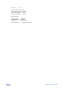
When the PC sends one of the commands in this group to the switcher, then, if the instruction is valid, the switcher
replies by sending to the PC the same four bytes that it was sent (except for the first byte, where the DESTINATION bit
is set high).
NOTE 3 - SETUP # 0 is the present setting. SETUP # 1 and higher are the settings saved in the switcher's memory, (i.e.
those used for Store and Recall).
NOTE 4 - The reply to a "REQUEST" instruction is as follows: the same instruction and INPUT codes as were sent are
returned, and the OUTPUT is assigned the value of the requested parameter. The replies to instructions 10 and 11 are
as per the definitions in instructions 7 and 8 respectively. For example, if the present status of machine number 5 is
breakaway setting, then the reply to the HEX code
0B 80 80 85
would be HEX codes
4B 80 81 85
NOTE 8 - The reply is as in TYPE 3 above, except that here the OUTPUT is assigned with the value 0 if the setup is not
defined / no valid input is detected; or 1 if it is defined / valid input is detected.
NOTE 13 - This is a request to identify the switcher/s in the system. If the OUTPUT is set as 0, and the INPUT is set as
1, 2, 5 or 7, the machine sends its name. The reply is the decimal value of the INPUT and OUTPUT. For example, for a
2216, the reply to the request to send the audio machine name would be (HEX codes):
7D 96 90 81 (i.e. 128dec+ 22dec for 2nd byte, and 128dec+ 16dec for 3rd byte).


Find Your Products By Category
Please Login
