
0
Owner's of the Kramer Electronics TV Cables Kramer Electronics TV Cables gave it a score of 0 out of 5. Here's how the scores stacked up:
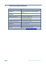

VS-66HN - Kramer Protocol 2000
25
10 Kramer Protocol 2000
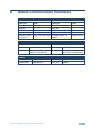
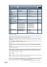
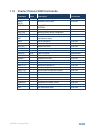
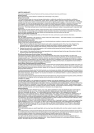
The Kramer Protocol 2000 RS-232/RS-485 communication uses four bytes of
information as defined below. All the values in the table are decimal, unless
otherwise stated.
MSB
LSB
1st Byte
DESTINATION
INSTRUCTION
0
D
N5
N4
N3
N2
N1
N0
7
6
5
4
3
2
1
0
2nd Byte
INPUT
1
I6
I5
I4
I3
I2
I1
I0
7
6
5
4
3
2
1
0
3rd Byte
OUTPUT
1
O6
O5
O4
O3
O2
O1
O0
7
6
5
4
3
2
1
0
4th Byte
MACHINE NUMBER
1
OVR
X
M4
M3
M2
M1
M0
7
6
5
4
3
2
1
0
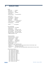
1st Byte: Bit 7 – Defined as 0
D – DESTINATION:
0 – Sends information to the switchers (from the PC)
1 – Sends information to the PC (from the switcher)
N5…N0 – INSTRUCTION
The 6-bit INSTRUCTION defines the function performed by the switcher(s). If a function is performed using the
machine’s keyboard, these bits are set with the INSTRUCTION NO. performed. The instruction codes are defined
according to the table below (INSTRUCTION NO. is the value set in N5…N0).
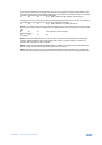
2nd Byte: Bit 7 – Defined as 1
I6…I0 – INPUT
When switching (i.e. instruction codes 1 and 2), the 7-bit INPUT is set as the input number to be switched. If switching is
done using the machine’s front panel, these bits are set with the INPUT NUMBER switched. For other operations, these
bits are defined according to the table.
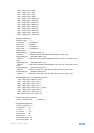
3rd Byte: Bit 7 – Defined as 1
O6…O0 – OUTPUT
When switching (i.e. instruction codes 1 and 2), the 7-bit OUTPUT is set as the output number to be switched. If
switching is done using the machine’s front panel, these bits are set with the OUTPUT NUMBER switched. For other
operations, these bits are defined according to the table.
4th Byte: Bit 7 – Defined as 1
Bit 5 – Don’t care
OVR – Machine number override
M4…M0 – MACHINE NUMBER
This byte is used to address machines in a system by their machine numbers. When several machines are controlled
from a single serial port, they are usually configured together and each machine has an individual machine number. If
the OVR bit is set, then all machine numbers accept (implement) the command and the addressed machine replies.
When a single machine is controlled over the serial port, always set M4…M0 to 1, and make sure that the machine itself
is configured as MACHINE NUMBER = 1.


Find Your Products By Category
Please Login
