
0
Owner's of the Kramer Electronics DJ Equipment Kramer Electronics DJ Equipment gave it a score of 0 out of 5. Here's how the scores stacked up:
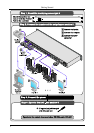
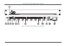
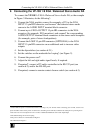
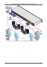
Connecting the VP-108 1:8 XGA / Balanced Stereo Audio DA
9
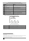
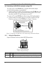
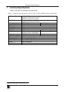
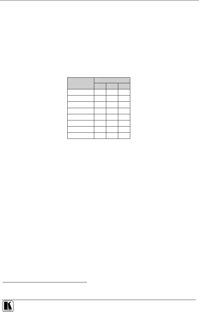
6.2.2 Setting the MACHINE #
The MACHINE # determines the position of a VP-108 unit, specifying which
VP-108 unit is being controlled when several VP-108 units connect to a PC
or serial controller. Set the MACHINE # on a VP-108 unit via DIPS 1, 2 and
3, according to Table 4.
When using a stand-alone VP-108 unit, set the MACHINE # to 1. When
connecting more than one VP-108 unit, set the first machine (the Master) that
is closest to the PC, as MACHINE # 1
1
.
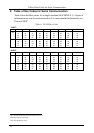
Table 4: Machine # Dipswitch Settings
DIPSWITCH
MACHINE #
1 2 3
1
Master
OFF
OFF
OFF
2 ON OFF
OFF
3 OFF
ON OFF
4 ON ON OFF
5 OFF
OFF
ON
6 ON OFF
ON
7 OFF
ON ON
8 ON ON ON
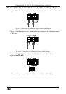
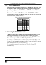
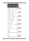
6.3 Connecting the REMOTE Connector
Connecting the REMOTE terminal block connector pins to a contact closure
switch lets you to disable (and then enable again) output(s) by remote
control
2
. To do so, touch (momentarily) the appropriate REMOTE terminal
block connector pin to the Ground PIN, as Figure 9 illustrates.
For example to disable outputs 1, 2 and 8, touch (momentarily) PIN 1 to the
Ground PIN, and then touch (momentarily) PIN 2 to the Ground PIN, and then
touch (momentarily) PIN 8 to the Ground PIN.
Do not touch (momentarily) more than one PIN to the Ground PIN
simultaneously.
1 Set the dipswitches to OFF
2 An output may also be disabled via RS-232 or RS-485


Find Your Products By Category
Please Login
