
0
Owner's of the Azden Mixer FMX-42 gave it a score of 0 out of 5. Here's how the scores stacked up:
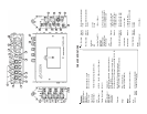

“INPUT LEVEL” Settings: “+4”, “-30 dBu”, “-50 dBu”
Each input channel of the FMX-42 has its own level setting (7). Select the input level
that is best suited for the microphone, wireless receiver or line-level audio compo-
nent that you are connecting to each input. The “+4” setting is for line-level audio, “-
30 dBu” and “-50 dBu” are both microphone-level settings. For the microphone-
level settings, start with the “-30 dBu” position. If your microphone seems to have too
much gain (volume) try the “-50 dBu” setting.
“PHANTOM DC48V” Switch:
Each channel of the FMX-42 has its own “PHANTOM DC48V” power setting (8).
When using a dynamic microphone be sure to turn the corresponding “PHANTOM
DC48V” switch to the “OFF” position. When using a condenser microphone that
requires 48VDC external power, turn the corresponding “PHANTOM DC48V”
switch to the “ON” position. The “PHANTOM DC48V” only opterates in the “-30
dBu” and “-50” “INPUT LEVEL” position
WARNING: With the “PHANTOM DC48V” power turned “ON” the FMX-42 supplies
48VDC to the microphone. Please make sure that your microphone is designed to
handle 48VDC or you may damage it. Check the microphone’s user manual or with
the manufacturer of your microphone.
FRONT PANEL CONTROLS and SETTINGS
Input “LEVEL” Controls:
Each “INPUT” channel of the FMX-42 has an adjustable input “LEVEL” control (9)
(this is the inner-smaller control). This controls the input volume of the microphone
connected to each corresponding “INPUT”. Zero is the lowest (quietest) setting
while 10 is the highest (loudest). For the best sound with the lowest noise, increase
the input level control until the corresponding VU Meter (10) peaks at 0 dB.
Input “PEAK” Level LEDs:
Each “INPUT” channel of the FMX-42 has 2 “PEAK” level LEDs. These LEDs are
provided to help set precise input “LEVEL” adjustments. The LEDs are located to the
left of each input “LEVEL” control. The lower LED (11) indicates the level of the input
electronically prior to the “LEVEL” control. The upper LED (12) indicates the level
electronically after the “LEVEL” control. The lower LED (11) lighting RED indicates
that the item attached to the mixer’s “INPUT” has a signal that is too high and should
be reduced either by changing the “INPUT LEVEL” switch (7) or at the device itself.
The upper “PEAK” level LED (12) should only light RED occasionally. If this LED
stays lit continuously lower the input “LEVEL” (9) and/or change your “INPUT
LEVEL” (7) settings. These LEDs help reduce signal overload and distortion.
“PAN” Controls:
Each channel of the FMX-42 has an adjustable “PAN” control (13) (this is the outer-
larger control). When the “PAN” control is in the center position, an equal amount of
sound will come from “OUTPUT” “L” (14) and “OUTPUT” “R” (15) for any micro-
phone or line-level input connected to the corresponding “INPUT”. Moving the
2
3
“PAN” control left will decrease the sound output in the “R”ight channel. Moving the
“PAN” control right will decrease the sound output in the “L”eft channel.
“LIMITER” Switch:
Each “INPUT” channel of the FMX-42 has a switchable “LIMITER” (16). After
setting the input “LEVEL”, turn this switch to “ON”. The “LIMITER” circuit acts as a
safety and reduces the possibility of overload distortion from very loud sounds
without affecting normal sound volume. If you prefer the overall sound quality of the
mixer without the “LIMITER” circuit engaged leave the switch “OFF”.
“HPF” - High Pass Filter:
Each “INPUT” channel of the FMX-42 has a switchable high pass (low cut) filter -
“HPF” (17). This filter is useful for removing unwanted low frequencies, such as
wind and air-conditioning noise. For most applications engaging the high pass filter
will improve overall sound quality.
“MASTER” Level Control:
The “MASTER” knob (18) controls the overall volume of all connected sources
(microphones and/or line-level devices). For the best possible sound and lowest
noise, try to keep this control set at its midpoint while maintaining the VU meters at
their 0 dB range with the “input “LEVEL’ controls.
VU Meters - “L” and “R”
For the best sound, while keeping the “MASTER” control at its midpoint, increase or
decrease each channels “LEVEL” control (9) until the “L” and/or “R” VU meter (10)
peaks at 0 dB. If the ”LEVEL” is set too low, sound may be accompanied by
background hiss. If the “LEVEL” is set too high the sound may be distorted. Monitor
the sound with headphones and adjust the “LEVEL” for the best sound. A peak level
LED (19) will light RED if your overall levels are set too high.
“SLATE MIC”:
Press and hold this button (20) to engage the “SLATE MIC” (microphone). The
“SLATE MIC” is used to pick up audio at the mixer’s location and is not intended for
serious audio recording. It is however, very useful for notating scenes or other on-
location documentation .
“1 kHz TONE”:
Press and hold this button (21) to generate the 1 kHz tone. This output tone is used
to set the recording levels of your video camera or audio recorder to their optimum
level. While generating the 1 kHz tone, set the recording levels of your video camera
or audio recorder to the specified level as recommend in the owner’s manual. The
signal is generated at +4 dBu.


Find Your Products By Category
Please Login
