
0
Owner's of the Rolls DJ Equipment RM82 gave it a score of 0 out of 5. Here's how the scores stacked up:
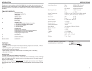
OPERATION
CONFIGURING THE 1/4” INPUT JACKS AS DIRECT OUTPUTS
The eight 1/4” Input jacks come from the factory configured as line inputs and are
electrically mixed with the XLR jacks. They may be used together if desired. To
configure a channel’s 1/4” jack as a Direct Out, first remove the RM81 lid. For
each channel there are dual three-pin headers with shorting jumper on two pins.
The setting from the factory is on “IN”. By moving the shorting jumpers to the
configuration shown as “OUT” (one jumper up, the other down), the jack then
becomes a Direct Output.
CONFIGURING THE 1/4” INPUT JACKS AS INSERTS
To configure a channel’s 1/4” jack as an Insert, first remove the RM82 lid and
locate the corresponding channel’s dual three-pin header. Move both shorting
jumpers down as shown below as “INSRT”, the jack then becomes an Insert.
Direct
Output
Insert Input
CONFIGURING THE OUTPUT FOR MIC OR LINE LEVEL
The RM82 ships from the factory with the XLR Main Output configured as Line
Level (+4 dB). To change this to Mic Level (-10 dB), carefully remove the lid, locate
the Mic/Line header which is near the Main Output jack. Move the two jumpers
from the Line Level position (shown below on the right), to the Mic Level position
(shown on the left).
Mic
Level
Line
Level
3 4
AUX
BUSS IN
PREFADE
OUT
MAIN
OUT
MODEL RM82
120 VAC
50/60 Hz 15 VA
MADE IN U.S.A.
SERIAL NUMBER
82-
PHANTOM POWER
8 7 6 5 4 3 2 1
WARNING:
CHANNEL 7
CHANNEL 8
on
AUX
BUSS IN
PREFADE
OUT
MAIN
OUT
MODEL RM82
120 VAC
50/60 Hz 15 VA
MADE IN U.S.A.
SERIAL NUMBER
82-
PHANTOM POWER
8 7 6 5 4 3 2 1
WARNING:
CHANNEL 7
CHANNEL 8
on
AUX
BUSS IN
PREFADE
OUT
MAIN
OUT
MODEL RM82
120 VAC
50/60 Hz 15 VA
MADE IN U.S.A.
SERIAL NUMBER
82-
PHANTOM POWER
8 7 6 5 4 3 2 1
WARNING:
CHANNEL 7
CHANNEL 8
on
SLAVE UNIT
MASTER UNIT
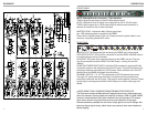
CONNECTION
1.
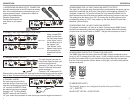
MICROPHONE AND MAIN OUTPUT CONNECTION
Connect microphones to the XLR Inputs as shown
here. If the microphones are condenser type, and
require phantom power - remember to switch on
(down) the corresponding
Phantom Power switch.
Connect the Output to the
next device in your signal
chain.
AUX
BUSS IN
PREFADE
OUT
MAIN
OUT
MODEL RM82
120 VAC
50/60 Hz 15 VA
MADE IN U.S.A.
SERIAL NUMBER
82-
PHANTOM POWER
8 7 6 5 4 3 2 1
WARNING:
CHANNEL 7
CHANNEL 8
on
AUX
BUSS IN
PREFADE
OUT
MAIN
OUT
MODEL RM82
120 VAC
50/60 Hz 15 VA
MADE IN U.S.A.
SERIAL NUMBER
82-
PHANTOM POWER
8 7 6 5 4 3 2 1
WARNING:
CHANNEL 7
CHANNEL 8
on
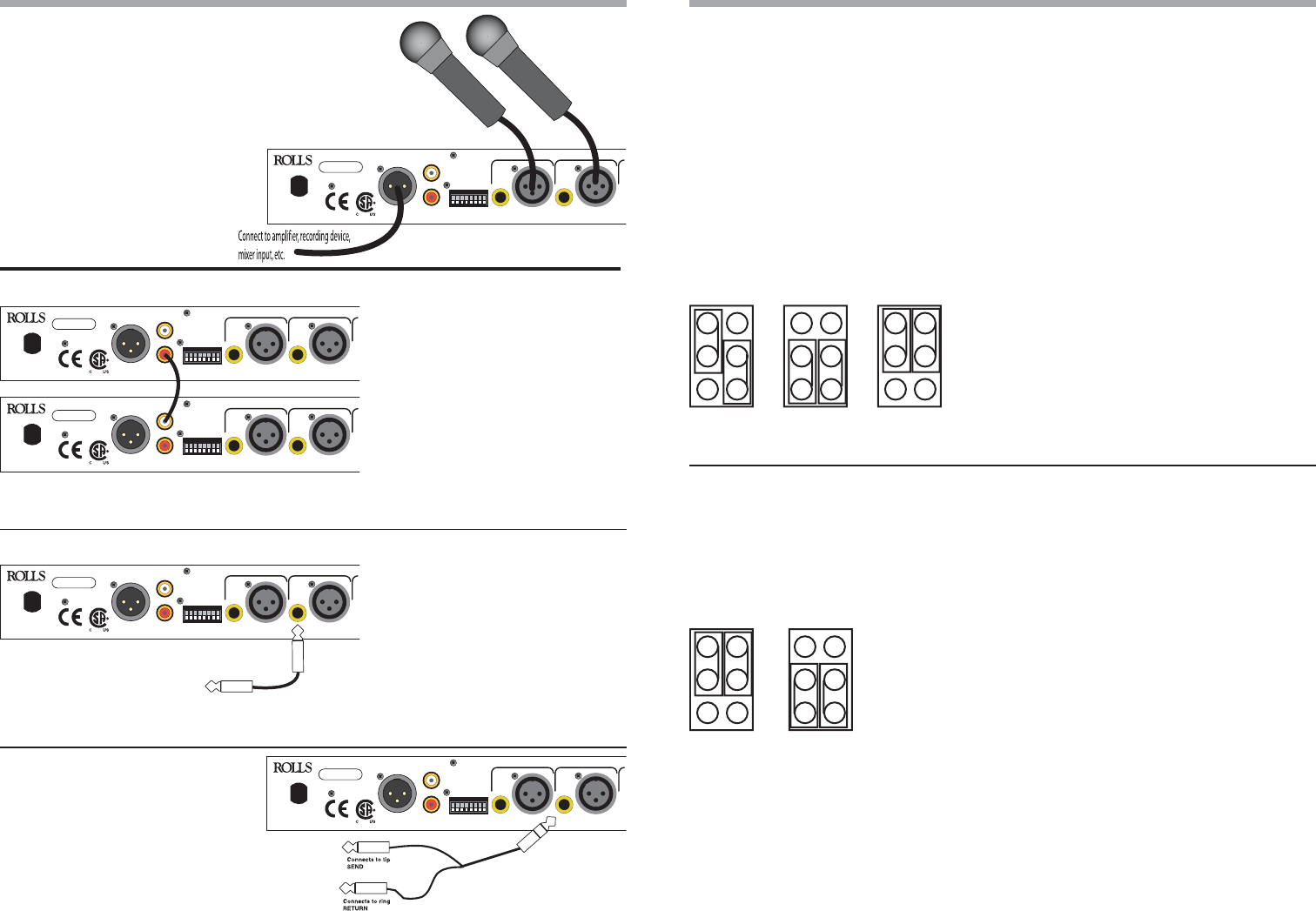
2. CONNECTING TWO RM82 UNITS TOGETHER
Using a single RCA
cable, connect from
the Pre-Fader Output
of the “Slave” unit to
the Aux Bus input of
the “Master” unit.
This “Master” unit’s
Master Level control
will now adjust the
overall level of both
units.
4. CHANNEL INSERT
For each channel you wish to
have the ability to insert into, you
must first configure that channel’s
1/4” Input as an INSERT. Follow
the instructions shown on page 4.
Connect a 1/4” Tip-Ring-Sleeve
INSERT cable into the channel’s
1/4” jack, and to the processor or other device you want the signal connected to.
3. CHANNEL DIRECT OUTPUT
For each channel you wish to
have Direct Output access, you
must first configure that
channel’s 1/4” Input as a Direct
Output. Follow the instructions
shown on page 4.
Connect a 1/4” unbalanced Tip-
Sleeve cable to the channel’s 1/4” jack and to the next device you want the signal
sent to. Note, the channel’s signal will still be present at the RM82 Main Output.
JUMPER DEFAULTS
The internal jumpers are configured from the factory as follows:
1/4” = INPUTS
MAIN OUT LEVEL = LINE LEVEL


Find Your Products By Category
Please Login
