
0
Owner's of the QSC Audio Car Speaker QSC Audio Car Speaker gave it a score of 0 out of 5. Here's how the scores stacked up:
10
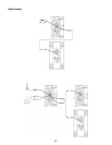
Input Connections
K8, K10, K12
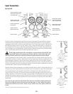
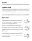
The K8, K10 and K12 are designed to accept MIC Level and Line Level inputs with several different connectors.
There are three input connection points on the input panel. Channel A will accept MIC or Line Level inputs by
connecting a male XLR cable or a male 1/4" phone cable (either TS or TRS type may be used). For MIC Level, the
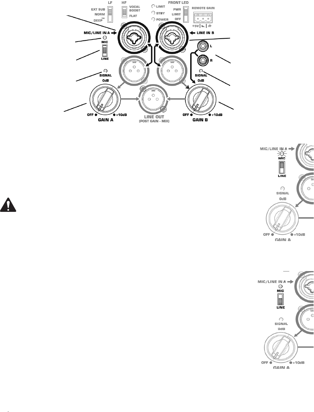
MIC/LINE selector switch must be in the “MIC” position. (Figure 5) When the selector switch is in the MIC posi-
tion, activating the MIC Pre-amp, the yellow MIC level LED indicator will turn on. The MIC setting should only be
used if a microphone is connected directly to the MIC/LINE input. Note that the input does not provide phantom
power. The LINE setting should be used for most other audio inputs. (Figure 6)
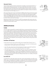
The MIC setting should only be used if a microphone is connected directly to the MIC/LINE input.
Using the MIC setting for other purposes may introduce distortion. Care should be taken when
switching to the MIC position as the output level will increase significantly when the switch is flipped.
Gain for signal delivered on the Channel A XLR/1/4" combination jack is set using the Channel A Gain knob. This
control sets the sensitivity of Channel A, and thereby the amount of signal sent to the power amplifier and, in turn
to the loudspeaker components. It also sets the amount of signal sent to the Post-Gain Line Output. The green
SIGNAL LED will illuminate when signal is present, regardless of the amount of gain as set by the Gain knob. If the
LED does not illuminate, the input is not receiving any signal or the level of the signal is significantly low. Check all
connections and the status of the device delivering the signal.
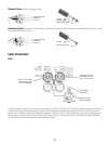
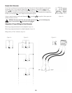
Channel B will accept Line Level input only, by connecting a male XLR cable or a male 1/4" phone cable (either TS or
TRS type may be used). Channel B will also accept mono or stereo Line Level input on a pair of RCA (phono) jacks.*
Gain for signal delivered on the Channel B line level XLR/1/4" combination jack and RCA (phono) jacks is set
using the Channel B Gain knob. The Channel B Gain knob will control the input gain of Channel B, as well as the
amount of signal sent to the Post-Gain Line Output. The green SIGNAL LED will illuminate when signal is present,
regardless of the amount of gain as set by the Gain knob. If the LED does not illuminate, the input is not receiving
any signal, or the level of the signal is significantly low. Check all connections and the status of the device deliver-
ing the signal.
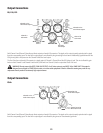
Note: Unless the gain controls associated with all active inputs are set to 0 dB, the output signal from the
Post-Gain Line Output will not be at the same level as the input signal. If a “slave” speaker is intended to
playback at the same level as the “master” speaker, the gain control on the “slave” speaker should be set
to 0 dB.
*Stereo input received at the RCA input jacks will be summed to mono.
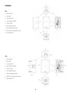
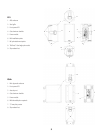
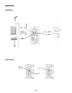
Channel A MIC/Line Input
Combination XLR-M and
1/4" Phone Jack
Channel A MIC/Line
Level Switch
Channel A MIC Level
Yellow LED Indicator
Channel B Line Input
Combination XLR-M
and 1/4" Phone Jack
Channel B Line Input
Phono (RCA) Jacks
Channel A Gain
Channel A Green
Signal Present LED
Channel B Gain
Channel B Green
Signal Present LED
– Figure 5 –
– Figure 6 –


Find Your Products By Category
Please Login
