
0
Owner's of the Kramer Electronics TV Cables Kramer Electronics TV Cables gave it a score of 0 out of 5. Here's how the scores stacked up:
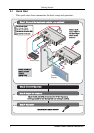

Your Audio/Video Line Transmitter and Line Receiver
7
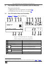
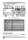
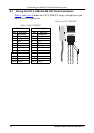
4.2 Your TP-10 Audio/Video Line Receiver
Figure 3
and Table 3 define the TP-10 unit:
Figure 3: TP-10 Audio/Video Line Receiver
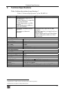
Table 3: Features and Functions of the TP-10
# Feature Function
1 CV OUT BNC Connector Connects to the composite video acceptor
2 Y/C OUT 4-pin Connector Connects to the s-Video acceptor
3 LINE IN RJ-45 Connector Connects to the LINE OUT connector on the TP-9
1
4
AUDIO
OUT
S/PDIF RCA
Connector
Connects to the digital audio acceptor
5 ANALOG 3.5mm Mini
connector
Connects to the analog audio acceptor
6
12V DC
+12V DC connector for powering the unit
7
LINK
AV LED Illuminates when receiving the correct input signal
8 IR LED Illuminates when receiving signals from an IR remote
control transmitter
9
IR SENSOR
IR sensor red glass window
10
CV/Y
EQ. Trimmer
2
Adjusts
3
the video EQ. (equalization) compensation
11 LEVEL Trimmer
2
Adjusts
3
composite video output signal or Y output signal
12 C LEVEL Trimmer
2
Adjusts
3
the C output signal
13 ON LED Lights when receiving power
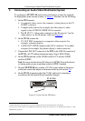
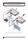
1 Using a straight pin to pin UTP cable with RJ-45 connectors at both ends (the PINOUT is defined in Table 4 and Figure 6)
2 If necessary (for example, when using a long cable), the adjustment range may be improved by opening the TP-10 cover
and shorting the following jumpers: J9, for equalization, J7, for CV or Y levels, and J8, for C level
3 Insert a screwdriver into the small hole and carefully rotate it, trimming the level
1
1
7
7
4
4
10
2
2
8
8
5
5
11
3
3
9
6
6
12
13
13


Find Your Products By Category
Please Login
