

0
Owner's of the JVC Flat Panel Television JVC Portable Monitor gave it a score of 0 out of 5. Here's how the scores stacked up:
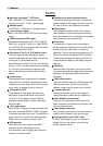
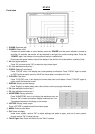
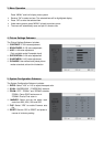
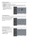

9. FUNCTION KEY Settings Submenu
The F KEY Settings Submenu is to define
Function Keys on the front keyboard.
The DT-X71F has 3 function keys:
F1, F2 and F3;
The DT-X71H and DT-X71C has 2 function
keys:
F1 and F2.
The available function items of each model are:
-------------------DT-X71F-------------------
-------------------DT-X71H-------------------
01-RATIO: Aspect ratio switch
01-RATIO: Aspect ratio switch
02-SCAN: Underscan / Overscan switch
02-SCAN: Underscan / Overscan switch
03-ZOOM: Picture Zoom-in
03-ZOOM: Picture Zoom-in
04-PIC. MODE: Preset picture mode switch
04-CLR.TEMP: Color-temperature switch
05-B/W: Color / Black & white switch
05-PIC MODE: Preset picture mode switch
06-BLUE ONLY: Blue only mode switch on/off
06-B/W: Color / Black & white switch
07-ZEBRA: Zebra over exposure switch on/off
07-REVERSE: Image flip
08-VECTOR: Vector scope switch on/off
-------------------DT-X71C-------------------
09-PATTERN: Internal colorbar switch on/off
01-RATIO: Aspect ratio switch
10-RGB HIST: R, G, B Histogram switch on/off
02-SCAN: Underscan / Overscan switch
11-TIMECODE: SDI timecode display switch on/off
03-ZOOM: Picture Zoom-in
12-F.COLOR: False color mode switch on/off
04-CLR.TEMP: Color-temperature switch
13-AUDIO BAR: Audio meter display switch on/off
05-PIC MODE: Preset picture mode switch
14-FOCUS: Peaking focus assist switch on/off, and
06-B/W: Color / Black & white switch
red/blue selection
07-REVERSE: Image flip
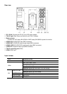
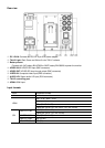
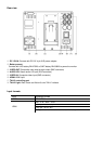
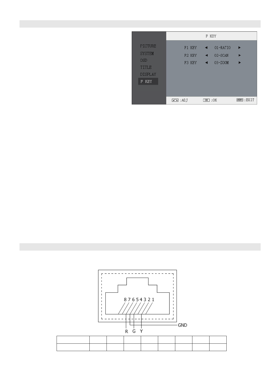
10. TALLY Light Operation
There are front and rear TALLY lights on the monitor, which can display RED, GREEN and YELLOW signals.
The TALLY light controlling port is the RJ45 socket at the rear panel, and terminal description is as follows:
The RED light is on when connecting the terminal “R” with “GND”, and goes out when disconnecting.
The GREEN light is on when connecting the terminal “G” with “GND”, and goes out when disconnecting.
The YELLOW light is on when connecting the terminal “Y” with “GND”, and goes out when disconnecting
Terminal
1
2
3
4
5
6
7
8
Description
Y
G
GND
R


Find Your Products By Category
Please Login
