
0
Owner's of the CHIEF Projection Television CHIEF Projection Television gave it a score of 0 out of 5. Here's how the scores stacked up:
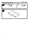
Installation Instructions LPK1
5
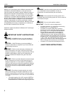
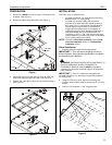
PREPARATION
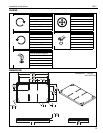
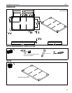
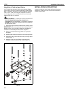
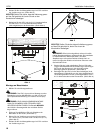
1. Remove and SAVE four nuts from top of VCM mount (not
included). (See Figure 1)
2. Remove and discard top slide plate. (See Figure 1)
Figure 1
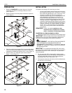
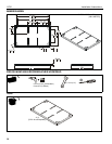
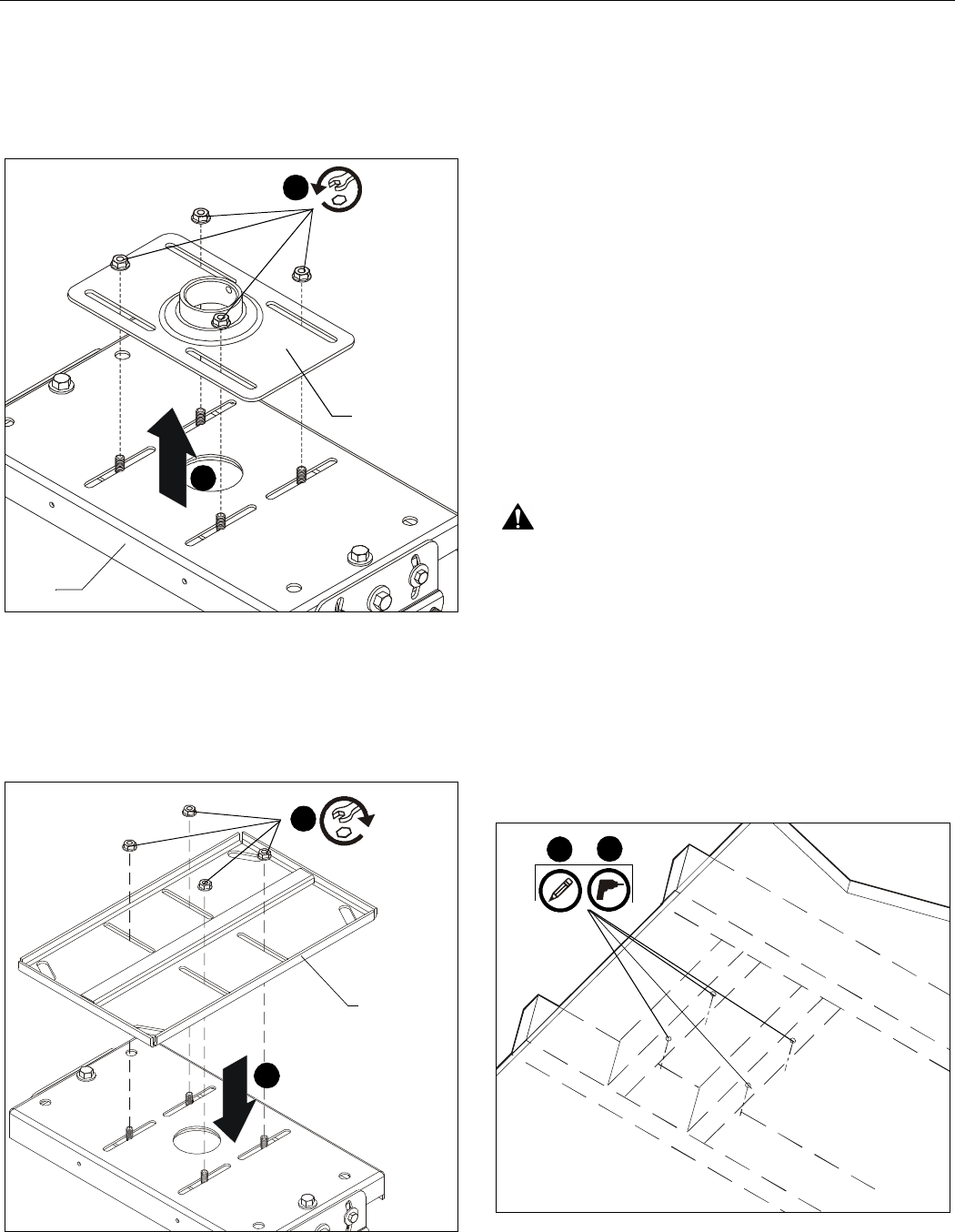
3. Place LPK1 mount (A) open side up on top of VCM, with
VCM studs fitting through LPK1 slots. (See Figure 2)
4. Tighten LPK1 (A) in place using four nuts removed in Step 1.
(See Figure 2)
Figure 2
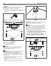
INSTALLATION
The LPK1 mount is designed to be:
• mounted to double 2" x 4" wood stud cross bracing
between two 2" x 4" ceiling joists;
• mounted to a concrete ceiling with a minimum
thickness of 8" and a maximum drywall covering of
5/8" using 5/16" x 2-1/2" lag bolts (not included) for
Fischer UX8 concrete anchors (not included) or
Toggler AF8 concrete anchors (not included); or
• suspended from four 3/8 in. diameter ASTM A307 or
stronger threaded rods (not included) which are
secured to a 1-5/8" x 1-5/8" 12ga metal framing strut
channel (spanning a maximum of 4 feet--not included)
by 3/8" channel nuts (not included).
NOTE: Proceed to Wood Stud Installation section, Solid
Concrete Installation section, or Threaded Rod
Installation section.
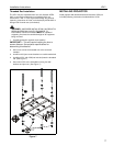
Wood Installation
1. Carefully determine required mounting location.
IMPORTANT ! : This will require knowing the lens to
screen distance. See projector specifications for details
on determining this distance.
WARNING: IMPROPER INSTALLATION CAN RESULT IN
SERIOUS PERSONAL INJURY OR DAMAGE TO
EQUIPMENT! Structural members MUST be capable of
supporting five times the combined weight of all equipment
being mounted.
IMPORTANT ! : The LPK1 mounts are designed to be
mounted to double 2" x 4" wood stud cross bracing between
two ceiling joists.
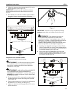
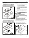
2. Using the LPK1 as a guide, mark four mounting hole
locations. Hole locations must be centered on 2" x 4" cross
braces.
3. Drill four 7/32" diameter x 1-3/4" long pilot holes.
Figure 3
Top slide
plate
1
x 4
VCM
2
3
x 4
2
(A)
2
3
x 4


Find Your Products By Category
Please Login
